TRIACs are strange beasts. The operate in 4 quadrants, that is most of them can. As far as I know they all can operate in 3 quadrants and some in all 4.
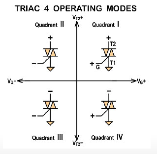
The modes are a combination of the gate voltage polarity and the T2 voltage. T1 is referenced at ground. So T2 can be positive compared to T1 with a positive gate, that is called quadrant 1. Above you see the 4 quadrants. Quadrant 4 is T2 more negative then T1 with a positive gate.
The datasheet tells you if it is working in 4 quadrants or just 3. If it is 4 then be warned that Q4 has other parameters as the other 3. For instance to fire a BTA26-600 you need only something like 30 to 50 mA to fire in Q1`, Q2 and Q3, but to fire in Q4 it needs 50-100 mA. If a TRIAC is fired (switched on) it needs a minimum amount of current to stay on. In Q4 it often needs more current.
I made this tester so I can test all 4 quadrants. Why, you ask ? Well because there are circuits that use all 4 quadrants. If you look at the first picture you see the only difference between Q1 and 4 is the T2 voltage. the Vg is positive. If you use it to switch AC and control the gate with a microcontroller. You use Q1 and Q4. The Vg is always positive and T2 sees AC, so it switches between positive and negative.
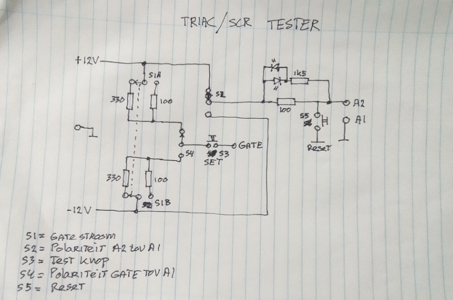
My first version, see the schematic failed to fire the BTA26 in Q4. I already had added a switch to be able to use a 100 mA gate current (30 mA or so is enough for a lot of TRIACs but bigger ones need more gate current. But that did not help. I then changed the T2 resistor for a 33 ohm because a TRIAC only stays on if the T2 current stays above the hold current. For Q1 to 3 it works fine with 30 mA gate and 100 mA T2 current, but for Q4 it needed 100 mA and more then 100mA hold current. The 33 ohm gives around 330mA and that is enough. You select the quadrant you want to test, momentarily press test and the green led goes on and stays on until you press reset. Green goes on for Q1 and Q2, red for Q3 and Q4. The red led left of the green one is just to show power is on. Left are three banana busses for power input from a lab supply. Red = +12, Black = 0V (gnd), blue = -12V. On the right red for T2, Black fot T1 and blue for the gate. The 100 mA above ther test switch was the first edition, after changing the resistor for 33 ohm, it now is 330mA.
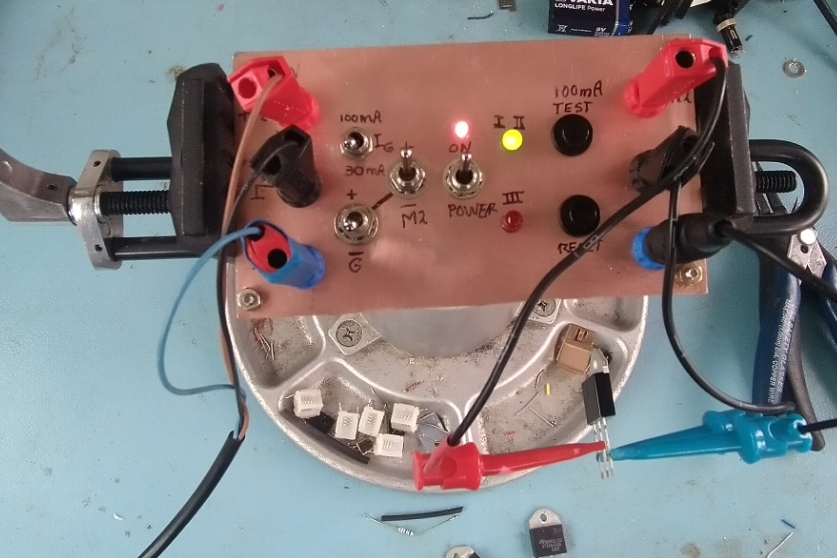
It is just a piece of PCB on 4 3cm bolts that act as feed. I had no cabinet on stock but I most times build these sort of things this way and store them in some small box. Easy to change things on the fly. For instance if I want more precise values I can easy short the 33 ohm temporary or the Vg resistors and use a current source to find the exact gate current and hold current for each quadrant.
I used +/-12V but this is totally not critical. You can use 5V or 24V as long as you adapt the resistor values. Just use Ohms law to find the correct resistor
You can use it to test SRC too, you only need Q1 for them. So the gate positive and T2 positive.
In the schematic I use A instead of T. In the past they used A1 and A2 but you also see M1 and M2, nowadays it is often called T1 and T2
Some measurements on a BTA26-600A:
The gate current to fire (330mA T2). I did not connect the gate to the tester but to a Source Measure Unit in current source mode.
Q1 12 mA
Q2 20 mA
Q3 16 mA
Q4 37 mA
De hold hold current for T2 and the fire current, (30 mA is the lowest current I could make without modification, I now inserted a 300 ohm potentiometer between T2 and the tester and used a DMM to measure.
The gate current switch is here in the 100 mA position.
……fire….hold
Q1 <30…..34
Q2 85…..35
Q3 <30….<30
A4 <30….<30