GR-900 LB slotted line

This is the GR-900 LB user manual (20 MB, over 80 pages in high res. Scanned by Guy,  who also has a GR-900 LB. The user manual for this slotted line is rather rare so I placed it on my site, you can download it from here: GR900slottedline_user This is a General Radio GR-900-LB. One … Read more

GR-1216A IF amplifier detector

Together with a unit oscillator http://www.pa4tim.nl/?p=4283  and the GR-874 MR mixer unit http://www.pa4tim.nl/?p=4686 this was part of a very flexible system to detect UHF and VHF signals. The AM signal is to be mixed to 30 MHz and then detected and amplified by the GR-1216A. It can be used as a RF voltmeter with a 100dB dynamic … Read more

GR-1603 ZY bridge

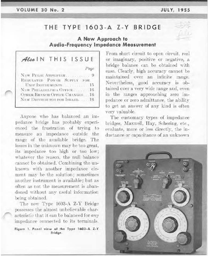
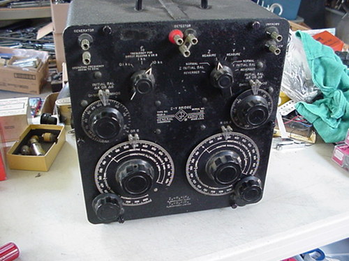
GR-1603A ZY bridge
GR-1603A ZY bridge


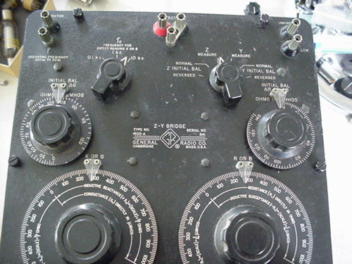
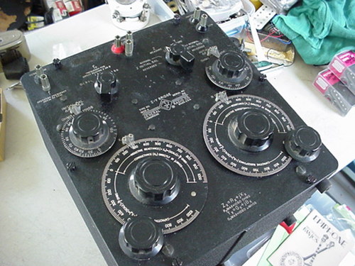
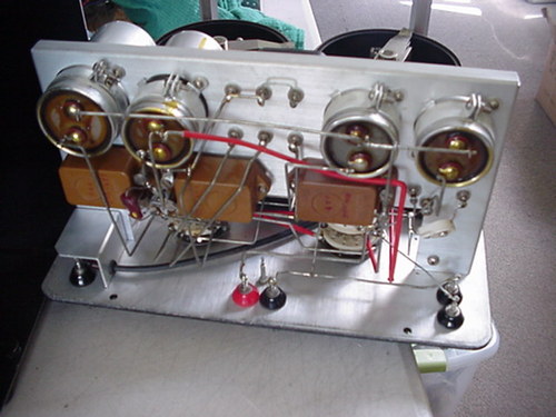
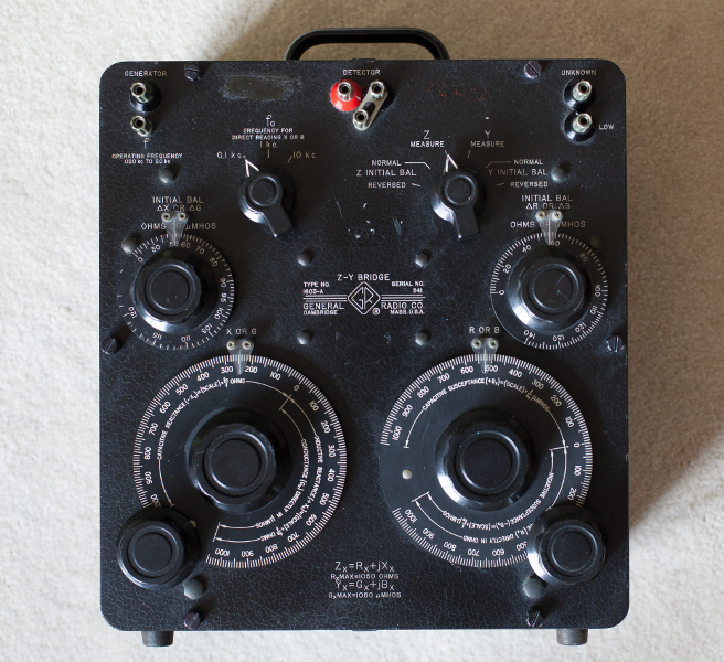
Thanks to my friend Ken for finding this beautifull bridge and sending it from the states to here. The nice pictures are made by Ken who even cleaned the unit before shipping.

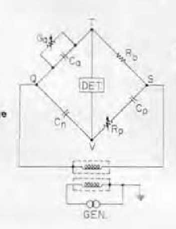
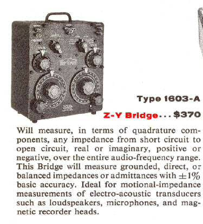
The GR-1603a was introduced in 1955.  It is able to measure Z in rectangular format. So Rs an jX and Y in G and jB. According to GR it was capable of measuring every impedance or admitance. But it is not a brifge for the faint hearted. It has 8 modes in which you have to do things in the right order, note some in between results and do some math to get the result.

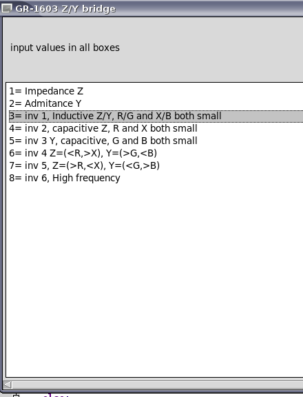
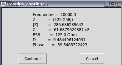
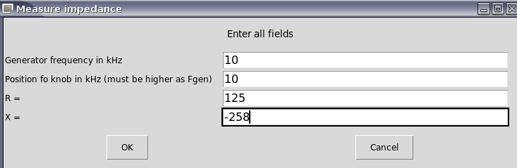
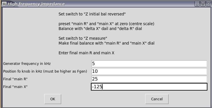
I wrote a program in Python to do the math for me. Here are some screenshots from the first tests. I have not checked all math yet but this is the code, just rename it to GR-1603_gui.py and run it as python GR-1603_gui.py or in Debian build it with Geany (you need the easyGUY lib ) and run it from the menu as terminal program and the command:
“python /home/your_name/your_dir/GR-1603_gui.pyc”

GR-1603A_python_programcode

(edit 5-7-013 new software version. Tested almost all modes exept 6-Y-inductive because I could not find a right component yet
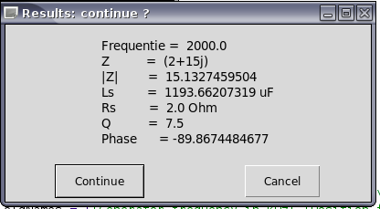
1603SW4

1603SW3 1603SW 1603SW2 1603SW1

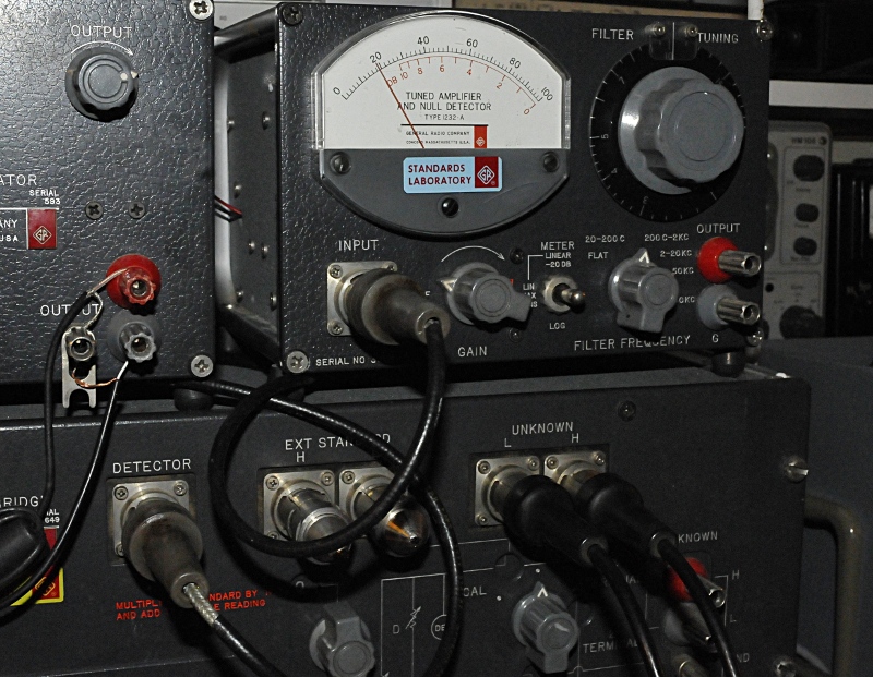
It needs a separate audio generator (20 Hz to 20 kHz, upto 150Vrms) and Detector. I have the original but for “mobile” use I will maybe make a small modern battery operated detector/oscillator unit. Down here you see the one that is on my GR1620 but I have a second one. Not as good as this one. It has a higher noiselevel so I must have some TLC. The problem is they need 12V made by 9 x M72 mercury Cells. They are very short “D” cell diameter cells and unobtanium. So I used an external 12V like my other detector. Today I made a battery replacement. It only draws a few mA (< 10 mA) so I took 4 CR lithium cells. Like you use in calculators. Put some shrinck tube around it and made a dummy pack. I soldered wires to them. Be carefull, better make contact strips. Lithium batterys do not like heat and can exoplode.
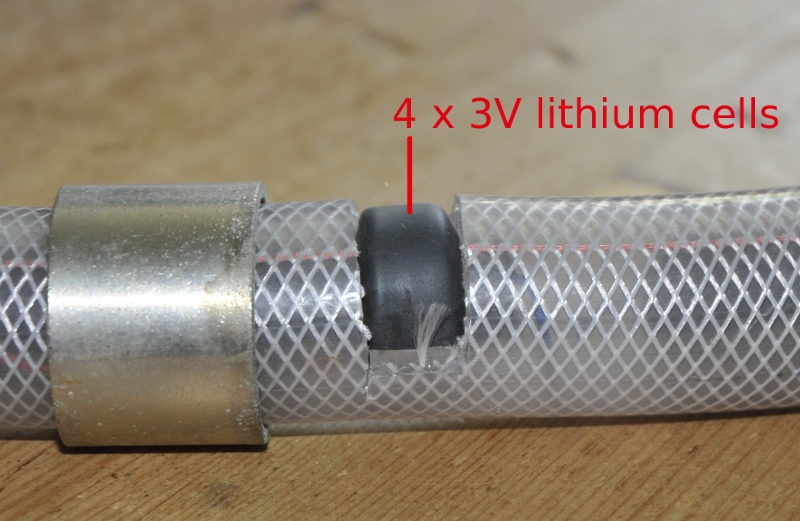
The hole that holds the 4 coin cells

I used a piece of airhose. That fits perfect. the metal ring is original and now is used to close the battery department. I made contacts from pcb and there is a core of foam in the hose that pushes out the pcb so it makes good contact. Nois level when zerod dropped from 40-20 on the scale.
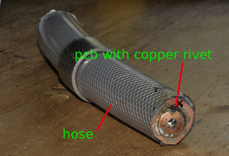
The dummy battery pack


de detector GR 1620
de detector GR 1620

It is AC coupled so you can measure DC biased components like batterys, powersupplys or DC behaviuor of electrolytic caps. It can also be used to measure the Zout of amplifiers or loudspeakers.

It is not the most accurate tool in the world but like GR told at the introduction, there is no other brifge that can do the same. It can measure everything from short to open. It it so so bad as some people think. If you use the different modes the right way it will supprise you. Mine needs a bit of recalibrating because if I zero the bridge and then measure open, short and load it is not 100% accurate. 50,17 Ohm reads as slight under 50, I guess around 49-50 Ohm (still better as many cheap multimeters) . For open you use Y, and that must be 0+j0. This reads G slight over 0 (about 0.05-0.1 umho I think) but that is > 10 MOhm and  a bit of dirt will cause the same leakage. A short with a groundstrap under the terminals reads in Z 0+j0.1 (also a rough estimation because the scale is coarse. In mode 1 or 2 you can measure this more exact. And at 10 kHz this should be lower. If I set the dials right and zero it with the delta sials too and use this setting, the other measurenents are correct. So for more accuracy there are some tricks. Just calibrate it like you do a vna and the measure the DUT.

But even like it is, it is more then close enough to be usefull for many things.

Because it is audio and 600 Ohm was the standard back then it is most accurate in that area. A simple trick is measuring very small impedances in series with a 600 Ohm resistor and very high ones with a 600 Ohm parallel and then calculate the right value back. If B or X is very lare or small you can do the same with a 600 Ohm or umho reactance. But most times the modes from table 2 in the manual give you a usable way without tricks.

I did some tests at 10 kHz:
a capacitor, 2,488 uF with a 0,18 Ohm ESR at 10kHz, that is Z=0,18-j6.23Ohm. The bridge measured 0.1-j6.6 Ohm or 2,49 uF
a torroid, 24.58 uH and Rs 0,14 Ohm. But the bridge measured with 3Vrms, that is a lot more as the LCR meters or mij L bridge and cores react on current. It measures 0.1+j1.85 or 29,4 uH.
A 85,2 pF cap measured in Y mode 92,9 pF.  that is 9% off but it can be better, It were just quick test. For instance if my generator was 100 Hz off the result will be different too. Best to measure this before serious measurements.
A 3,287 mH inductor with a Rs=28,7 Ohm measured Z=30+j209 and that is 3,326 mH so very close.

This is the impedance of a 600 Ohm headphones:
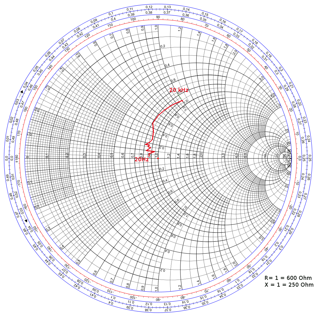
A 600 Ohm headphone from 20-20000Hz
bridge layout
bridge layout
Introduction from GR experimenter july 1955
before cleaning
before cleaning
front details
front details


Front
Front
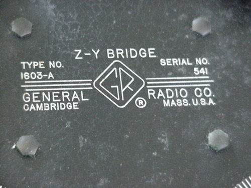
Type and serial number


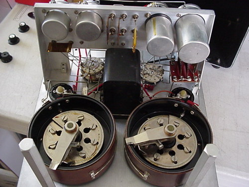
The two giant potetiometers
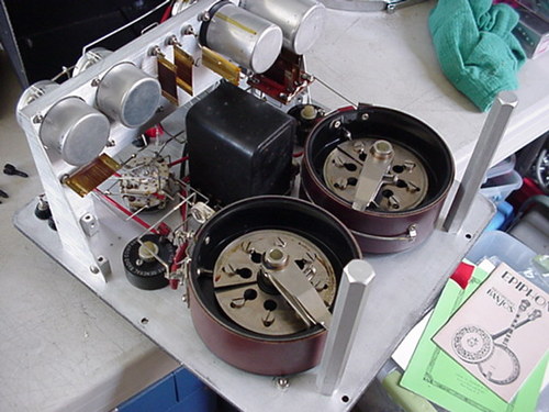
The inside from an other angle
The arm standards
The arm standards
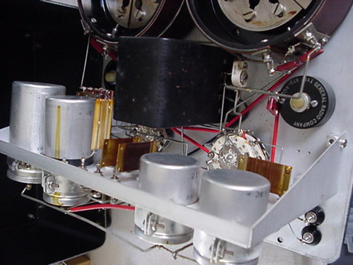
More details
More details

1603folder

Spectron datascope D301

This is as far as I could find, something used to measure signals between computers in the ice-age. It is dated 1978. It was hooked up between something like a mainframe and a printer or terminal and then they could watch serial signals. A sort of pre-historic LA. It seems do something, but I have … Read more

Tektronix RFM151 signal scout

Dit is een cai-kabel spectrum analyser maar hij heeft ok een paar leuke andere opties zoals veldsterkte meten en demoduleren. Hij loopt tot ongeveer 1GHz maar is niet zo gevoelig als een “echte” spectrum analyser. Hij was bedoeld om kanalen op kabel netwerken te monitoren en heeft daar veel functies voor. Hij was defect en … Read more

accessoires for scopes and analysers

When playing with measurement gear you need a lot of stuff to connect everything together in the right way. Things like adapters, couplers, bias-T’s, inline probeadapters etc. A lot of these thing are homemade. There is a lot of commercial stuff sold over the years but because of some strange unknown reason, these seem to … Read more

Mooi he, een SA uit 1961!

Ik heb hem niet hoor maar ik wilde het plaatje gewoon laten zien. Dit is het commentaar over het beest van een verzamelaar die er een heeft staan, (Tekst and Picture: Andrew Holme) This is a 30MHz SA with a 5inch P5 (or is it P7) phosphor long-persistence CRT. The only problem to you whereever … Read more

HP8558 Spectrum Analyser (SA)

Deze SA is naar een vriend toe in ruil voor een Tek SA Dit is de achterkant van het front. De schakelaars hebben zoals veel HP’s deze lipjes en als de herfst er aan komt vallen ze er af. Ik ga proberen hier iets voor te fabriceren. Als het lukt zal het hier vermeld worden … Read more

Selectieve voltmeter HP-312B

Een wave analyser , in Nederlands frequentie selectieve voltmeter of meetontvanger is een soort handmatige spectrum analyser. Zoals de HP8407 VNA kon worden uitgerust met meter ipv display, dan moest je wel met de hand sweepen, is dit een spectrum analyser zonder display. Er bestaat zelfs een HP-313A tracking generator voor. Hij gaat tot 18 … Read more

SDR-Kits VNWA

This  SDR-Kits 2 port VNA measures from 0.1 upto 1300MHz. It uses an internal directional bridge and many functions besides being a darn good VNA. It has the following functions: -VNA – Spectrum analyser (with tracking generator that can use an offset) – LCR meter – You can use it as counter and powermeter (max 0 … Read more

Russische SNA (RIP)

Dit is een russisch apparaat uit de jaren 80. Hij is volgens een stikker gebruikt door de universiteit van Berlijn. Het zijn twee enorme kasten maar het had makkelijk de helft kleiner gekund. Hij is net wat uitgebreider dan de gemiddelde wobbelaar maar het is ook weer geen echte scalar network analyser. Het is allemaal … Read more

My first networking steps

An old picture how my network analyse hobby started with an old russian SNA and aHP VNA Om snel te kunnen switchen tussen DUT en calibratie heb ik 4 shf coax relais gemonteerd. Alle kabels zijn voorzien van radial connectors en een goede kwaliteit RG58/U mil specs. De kabels zijn zo gemaakt dat ik net … Read more

Directional couplers en bridges

Dirctional couplers oftwel richtkoppelaars  en directional bridges zijn dingen die het mogenlijk maken om reflecties of power te meten. Er bestaan diverse varianten. Je kan ze maken met alleen weerstanden, met oppik “lijnen” (parallel draadjes zoals in een swr meter of microstrip op printplaat) en je hebt hybrides welke uit weerstanden en een balun bestaan. … Read more

HP-8407 VNA

This is a HP  vector network analyser. As far as I know it is  the first sweeping VNA.  It was intoduced in 1967 !  It has a plugin bay, something that was very populair in the 60-70’s. (and very handy too) You could get an analog meter to read Phase and return loss with high resolution but not … Read more

Nordmende UWM346/U-2 wobbulator

Not in my collection anymore, I have given it to a friend Alleen al het feit dat het een wobbulator is maakt hem al mooi. Klinkt toch stukken beter dan sweepgenerator of networkanalyser waar het de voorloper van is. Het is een ding om filters af te regelen. Hij bestaat uit twee delen. Het ene … Read more

TRM3 Sweepgenerator

EX US army sweeper. It is made to test filters from receivers and transmitters. It operates at 115V. I have the original manuals. It uses 50 Ohm. The sweep range is from 15MHz to 400 MHz. It is made from 1958 upto about 1965. It needs a coupler and diode detector. manual.pdf.tar manual2.pdf.tar