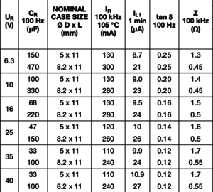
Part of a Vishay datasheet.
There are many misunderstandings about measuring electrolytic caps and their ESR.
99% of the ESR meters are hobby instruments and more indicators as meters. However they can be usable if you understand how to use them and what they measure. They are more or less only populair in commercial consumer stuff repairs and hobbyist who do the same. Have you ever seen a Keysight or Fluke ESR meter ?
Good LCR meters can measure ESR, or better AC resistance, at several frequencies. But also measure the more important D.
Datasheets most times state the capacitance at a stated frequency, impedance Z at 100 kHz (Z is not ESR) and the dissipation factor D (= tan δ = DF) the max allowed ripple current and the min/max values over time for these parameters. Often a multiplication factor for the current at different frequencies.
They also state limits, like max D new and f.i 200% of new D after using it a while. They almost never state the ESR at 100 kHz for through hole caps. You can calculate ESR from D but that is for the frequency stated for D. Often 100 or 120 Hz (it was decennia long 1 kHz but caps above 1000 uF are hard to measure at 1 kHz. Back then those caps were rare.)
More on ESR: http://www.pa4tim.nl/?p=3775
Some info about measuring bad caps: http://www.pa4tim.nl/?p=3331
You can measure in circuit, but the problem is that it is non-conclusive. A high ESR will most times be a bad cap. The problem is that if you measure a low ESR, it not always is a good cap. If there are good caps parallel (common on power rails) a cap with a sky high ESR will still measure good. Besides that, you do not know how to interpreted the measured value. You need some table but the once you find on the web, differ so much, they are of little use. Best way to go is make your own but the problem is that f.i. a 100 uF cap A from brand B is new 0.1 ohm and the 100 uFcap C from brand D is 1 ohm new. So a D of 1 is bad for the first one, but good for the other one. People who made the tables on the web have the same problem as you will have. They are practically based on nothing. If you repair TVs you often know the problems or can find info on forums or databases from your company and then an ESR meter can speed up things. You then probably now cap C4 must read under 0.3 ohm in situ.
Use it only to find the really dead once, in repairs that will not power up. Replace them and if that does not help, desolder and test the rest. If that does not work either…do some real trouble shooting.
Measurements out of circuit:
The good way:
– Take a LCR meter that gives you D (=tan d).
– Look up the datasheet
– lookup D (=tan d = DF = 1/Q = related to loss angle)
– and the frequency they measured that, often 100 or 120 Hz (it was 1 kHz for a long time)
– lookup the max value of D, most times 200%
– Take a real LCR meter, set it at the stated frequency
– Measure C, is it within specs ? often +/- 20% when they are new, how low the circuit tolerates is an other question.
– A real LCR meter or bridge will give you D
– If both are within specs the cap is good. If you want to go all the way you can measure leakage. (often stated for 2 or 3 minutes, this is not the working voltage leaking test, that is a test you do for safety.)
The easy way, but not always a good way
– replace the caps by the same brand and type new ones (nothing wrong with this)
– or with a suitable replacement with the same specs (you hope)
– do not kill the pcb by using crappy desolder tools
– this did not help ? Do some real trouble shooting with things like a scope and multimeter.
I only repaired 3 TV’s and non of them had dead electrolytics. (a shorted 1 nF 1kV cap, a dead 4 MHz Xtal and a shorted mosfet) but my satellite receiver needed over 40 new caps.
The hard way:
– fire up your ESR indicator
– measure the cap in circuit
– spend an afternoon looking for tabels that gives the ESR for 2 uF and works for your indicator (so a Z or an ESR table)
– Then decide witch table could be the correct one.
– After some hours you still do not know, so you start a bunch of new topics on some forums to get the same answer in all of them…or roll a dice
– before going mental you just replace all caps to be sure
4th way:
– Fire up your impedance meter (a sweeping one or a simple DIY self ESR meter that does not measure ESR but Z, how convenient 😉 )
– look up datasheet, note impedance Z at 100 kHz.
– if the measured Z is withing the stated specs, the cap is good.
5th way, involves some math:
– fire up your real ESR meter
– measure the ESR at 100 kHz
– look up the datasheet and note the impedance at 100 kHz
– calculate the reactance of the cap (based on C measured at 100 kHz ) 1/(2pifC) for instance 2,06 uF = 0.773 ohm
– calculate Z ; 1,2 ohm and 0.773 ohm makes: 1.427 ohm
– if Z is within the stated specs from the manufacturers datasheet, the cap is good.
6th way,
– take a scope
– probe the power rails
– if there is to much ripple, replace the cap.
– how high the ripple is allowed to be is stated in the service manual of the thing you repair.
– if it is not stated you must estimate that. Not to hard, measure on the Vcc pins of some components.
You need electronic knowledge for that but you need that for repair anyhow (only swapping maybe-dead caps and random components is not really repair)
The very bad way:
– every way that measures components in circuit >:-)
You can do that if you want to quickly find the real dead caps in something that is so dead you can not start it. Then remove and measure them using one of the ways above. Then start the normal trouble shooting.