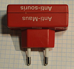
This is a dead anti mice thing you plug in a mains outlet. I had a dead one and was curious what was inside. The problem was a dead cap and some burned contacts. I wanted to know the kind of signal it generates so I repaired it a bit crude and show you the scope output.
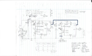
Schematic: I made a mistake with drawing the control voltage in the schematic. The one down here is correct.
How it works, I lost some footage so here the theory. Not a bad thing because I noticed while typing this I made a mistake while reverse engineering it.
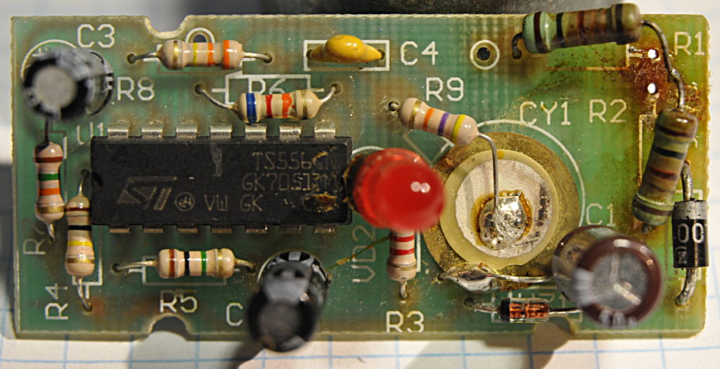
The 556 are two 555 timers in one IC. If we look at the first one (left) we see two resistors and a 1uF cap. The Vcc will charge the cap to a certain value. pin 2 is the input of a comparator and measures that voltage. When it reaches 2/3rd of Vcc, here around 3.3V it sets the internal flip flop. The result is that Pin 1, the open collector from a transistor switches on and goes low so the cap is now connected to ground and starts to discharge via R5 until the voltage on pin 1 is low enough to toggle back. The result is a triangle wave form at pin 2 and 6. As a result a there will be a squarwave with a frequency of around 0,6Hz. (According the formula in the datasheet)

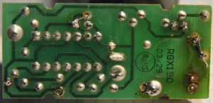
The bottom with burned traces
The C3 and R6 on the output of the first oscillator set the control voltage pin 11 of the second timer. This sets the threshold level and controls the frequency of the output of number 2. Thanks to the cap this level is not constant. The result is a changing threshold and that way a changing frequency of from the second oscillator. The base frequency of that one is around; 1,44/(15k+2x330k)x100pF = 22kHz Those values stay constant but are based on a fixed voltage of the threshold. So we get frequency sweeps with a sweep time of 1/0.6 = 1.7 seconds. This in theory, the values from the used components are never spot on so that is why we measured slightly different numbers.


