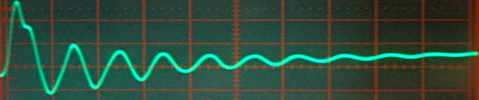
Non saturated coil
OK, you say, I have a LCR meter or a bridge so that’s a piece of cake. But inductors are kind a tricky when it comes to measuring. Especcially when they use core material. When I talk about inductors on this page, I mean inductors with cores. Beside self-inductance, an inductor has more parameters that are hard to measure, but they are important.
Some parameters I will talk about:
– self-inductance
– paracitics
– mutual inductance
– Q
– Current cooficient
– magnetic hysteresis
The real self-inductance is not a fixed value. It is determed by things like the Al of the magnetic material, the number of turns, wire diameter, size and form of core. But it is also influenced by the amount of current and the frequency. This makes it hard to predict if a coil made for a transmitter, filter or switching powersuppply will work as planned.
An inductor has also some capacitance, called distributed capacitance and this makes it has a selfresonant frequency. The inductive reactance ( +jX ) increases with frequency. But the reactance of the paracitic capacitance (-jX ) decreases. So the total reactance first increases until the point where they are equal but opposite in sign. That is self resonance (SRF).
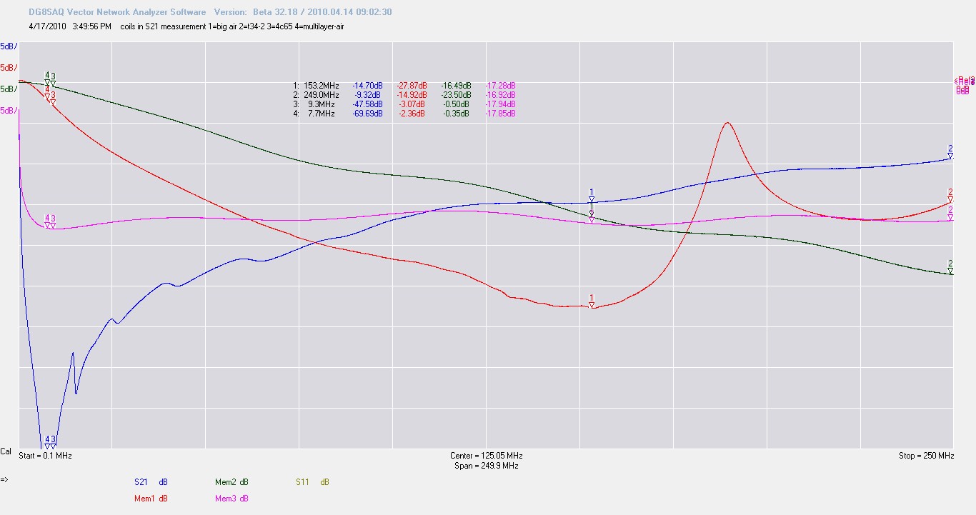
The reactance of an aircoil
This picture is maybe a bit complicated but is the damping of a signal that rises thanks to the frequency causing the reactance to increase ( of 4 aircoils). The lower the trace goes, the more damping. If we would use an ideal conductor (not inductor !) the trace would be on the top line of the graticule and plotted as 0 dB. It has no reactance or resistance. So if we look at the red trace we first see an increasing damping so the the impedance (apperant reactance and the real resistive part) must rise. The pure theoretical inductance does not change, the reactance changes, but because the distributed capacitance lowers the reactance, the apperant inductance seems to change too. At the the lowest point the capacitance takes the lead. Because of this the reactance decreases until they both are equal and a series resonance occures. You see that in the phase jump of the red trace in the next picture.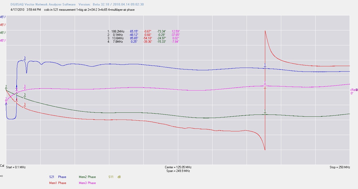
After this dull part of theory we will concentrate on the less known things.
A transformer is even more tricky to measure. The secundairy and primary windings influence each other. Part of the flux goes through the other winding and is ” lost ” for the first winding. So our LCR meter thinks the self inductance is higher as it really is.
We use a core because it increases the selfinductance. So we can get more inductance while still keeping the coil small. This proparty to increase selfinductance is called the Al of the core material. Often is it stated as nH per turns squared. So if this is 1000 and we use ten turns, L will be 1000 x (10 x 10) = 100000 nH or 100 uH. But this Al is also frequency and current dependend. So alway look in the datasheet or test it.
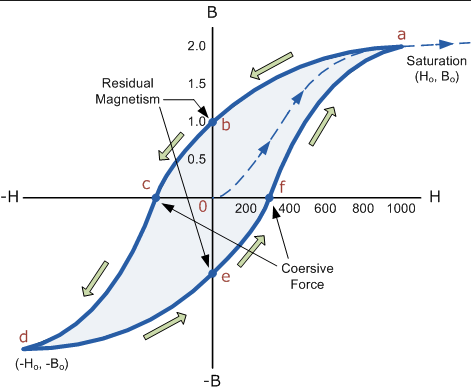
If we take some corematerial, the current through the inductor causes a magnetic field. The core material does not always like that. To tell it simplified, the core can not change at any speed, it needs some time, so if the AC signal changes sign the core must follow and change too. At a certain speed and at a certain current the core stops cooperating and saturates. The Al drops and so does the self inductance. The current sees less reactance and increases exponential. The core heats up and that speeds up the proces.
So it would be nice if we could test this. For this I made a saturation tester. http://www.pa4tim.nl/?p=1859
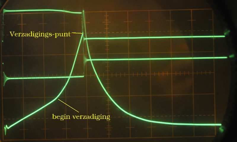
Als we de gate langer open sturen gaat het mis.
Here you see the saturation (verzadiging). Mainly by current because frequency is low. But there is an other test. You only need a sinewave generator, a resistor and a scope.
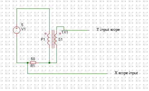
Setup
This will give you the BH curve of the core under current and frequency.
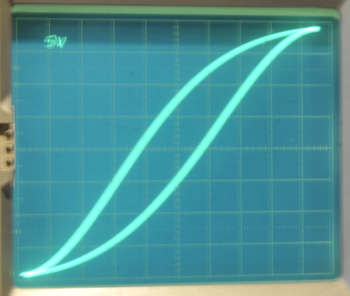
This will be the result. So without the math you can test for saturation.
The pictutre on top of the page is a non saturating inductor.
Here a youtube video about this subject from a very bright girl, Jerry Ellsworth:
http://www.youtube.com/watch?v=p7SkE5pERtA&feature=c4-overview&list=UUlTpDNIOtgfRkyT-AFGNWVw
To bad most generators can not deliver a lot of current, that way you can easy test a transformer at the working frequency and current, but you can use a variac or an old audio amp.
An inductor also has mutual inductance, part of the flux is ” lost” in the other winding. http://hyperphysics.phy-astr.gsu.edu/hbase/magnetic/indmut.html#c2 here you find a calculator. To see the effect just measure a transformer. First with the secundairy open, then with the secondairy shorted.
An example. I measured a ferite toroid with 60 turns of wire. This I measured with a L bridge. The value was 60 uH and Q was 0.85. Then I added a second winding made from only one turn of wire. With this 1 turn open, I measured 32.3 uH with a Q of 0.47, and with the second winding closed (Short) it was 33.5 uH and Q 0.5. So you see a huge difference with only one stinking turn of wire. The difference between open and short is not very big here, but with many turns this can be a big difference.
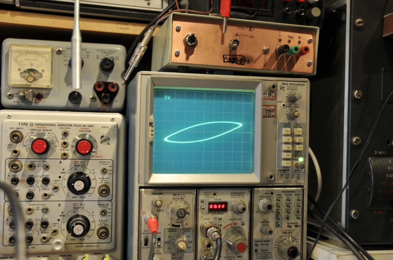
Then I tried the curve tracer. This is 50 Hz but can deliver a lot of current at a high voltage. So you can test for current saturation. A good transformer will give a circle. But if you increase current a BH curve like trace will appear. This is not a BH curve, it is a IV curve. But but you can see this as a “translation” or “relative” of the BH curve. The current rise causes the BH curve and the changing BH fields, increase current and so you get an avalanche effect. This was a very small transformer for safety. (saturating a 10A 230V transformer is not without danger.)
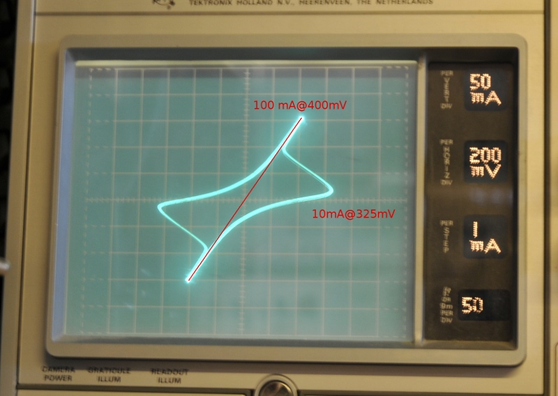
On the curvetracer
Just a little word about the Q. Many HAMs know this as something that has to do with bandwidth of a tank circuit or antenna. But Q has many faces. When we talk about an inductor or transformer the Q is nothing more as the inverse of the loss . The loss is caused by the real part of the impedance. An example, the inductor is 100 uH at 10 kHz and we measure a AC resistance at 10 kHz. The reactance Xl = 2.pi.f.L = 6.28j Ohm.
The AC resistance is for instance 2 Ohm. Then de impedance Z = (2+j6.28) if you then divide 6.28 by 2 you get a Q of 3,14 The bigger that number the smaller the loss is. This loss is from the copper, eddy currents, skin effect and coreloss . This heats up the transformer.
Why do I talk about measuring the resistance at AC ? That needs some explaining. Some of the loss resistance is real but still frequency dependend. If I jhad measured the DC resistance the Q would be higher because the frequency depened loss was invissible. Besides that, In this case I’m talking about the AC resistance as the real part of the impedance.
For those not familiar with the terms (see for instance my network tutorials or ESR pages):
Resistance, the value you measure with a ohm meter at DC. Some components are real but also frequency depending and in that case called AC resistance and it is the real part of impedance.
Impedance is the ” complex resistance” for AC. It is not a resistance you measure with an ohm meter, it is not that value for DC, because a capacitor has an infinitive DC resistance but can be a mOhm “resistance” for AC. So it behaves like a resistance.
The notation is |Z|, this is the absolute value notation. In our case the square root of R squared plus jX squared, that is 6,59 Ohm in the case of 2+j6,28. The j or i tell us it is a complex number. This means that we have information about the phase difference between current and voltage .
The impedance has two parts, the real part and the reactive part. The latter is called the reactance. The notation for that is Z =(R+jX) If jX is negative it is a capacitance, if it is possitive it’s an inductance. Our example: Z=(2+j6.28) That is the rectangular notation. It can also be written in a polar form. Z=(|Z|, phase angle) so Z = (6.59 , 72.3 degrees )