For a good performing switching psu the inductor is the most important part. Jim Williams talks about this in Appnote 25 (see link below) . If the current is to high the inductore core saturates. Saturation is the result of to much current through the core material. The changing current causes polarisation from little particles in the core material. You can see it as a whole bunch of little compass needles. All pointing in de changing direction of the fluxlines. If the current becomes to large (more current over the same time, or the same current/time but now over a longer time) they stay more or less fixed. DC current saturation is the same principle. (to calculate of the current, dutycycle, voltage and selfinduction are “matched” you can use: I=(V.t)/L) )
This tester lets you test an inductor. The schematic of the first version comes from this site:
http://www.dos4ever.com/flyback/flyback.html#ind2
I place the schematic from that (very informative) site for convinience:

I needed a very big psu for this test because my lab supply did not liked the voltage spikes caused by the inductor under test on his output.
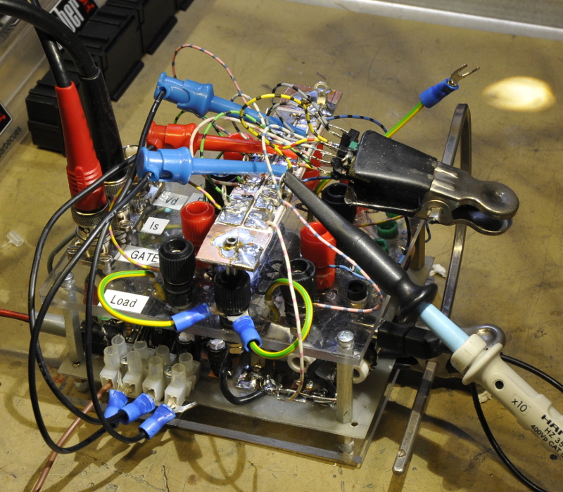
Some changes I made in a later model (jan 2012) are so that I can use my AC/DC P6042 current probe. Simulations showed that a good improvement would be to add a load. The resistor is 100 Ohm. You see the difference in the pictures. Much better and now I can use my other PSU’s without problems.
Very good reading material: AN 25, Lineair Technologie Switching Regulators for Poets. A Gentle Guide for the Trepidatious. Jim Williams. September 1987
www.linear.com/docs/4120
The image of the first version:

The upper trace, with the red dots, is the Voltage over the resistor. And so by Ohms law a measure for current. 100 mV=1A . It is an inverted trace. So the current is increasing while the trace goes down. The trace is from a normal good working inductor. If the trace shoots down the core is saturating. The core material can not keep up with the current. This causes an decreasing selfinductance. Less selfinductance is less reactance so more current will flow. If that happens, things go very fast. More current, less reactance, even more current unitil the powersupply reached its max or the inductor looses its magic smoke . Often you can hear the inductor screaming if a core saturates at audio frequencies
This version has a fixed frequency. A better setup would be the use of an external pulsgenerator to test at the working frequency but upto now I have very good results with this one.
This is how it looks now:
I use a differential probe here instead of a current probe. The trace is not inverted here.


If dutycycle increases the inductor core will saturate. You see it in this picture (saturate = verzadiging)

The simulation to check if I do it right.

Green is the current , blue the gate drive. If the gate goes high the Fet starts conducting. (Blue line goes up). The inductor is switched to ground and a current starts to flow. A magnetic flux is produced in the inductor. The inductor fights against the increasing current. If the gate becomes low the fet stops conducting and the current flows into the load. In an attempt to keep his state the inductor Voltage goes up. (the red line) If he rans out off flux the current drops to zero and the voltage decreases. After that you can see some ringing.

You can increase the duty cycle and load the inductor upto the point there is so much flux the core can not hold it and saturates. The selfinductance drops down and current shoots up, the coil becomes a short.

The purpose of a switcher is storing energy in the inductor in the form of a magnettic field. It looses the energy as current in the load. And after this the inductor gets charged again but you have to stop charging before saturation. This is done by the duty cycle. By increasing the frequency and or dutycycle you can transport a huge amount of current in many small parts. It is like filling a bathtub with 1 bucket (dutycycle is the size of that bucket) a minute (the frequency. This will take a while if you have one man with a small bucket. But if 100 men can empty 100 of those buckets in the same time you are quickly ready. And if you give those men bigger buckets it speeds up the process. That is, as long as the men can lift the buckets. If that becomes to hard they start to whine, just like the inductor does.
In fact, a classic lineair power supply does something similar. The transformer delivers current to an electrolytic cap. The cap wants to keep the voltage constant, 50 ot 100 times per second the cap gets loaded by a voltage going from Vt to zero. In the mean while, the load draws current from the cap. If the load is pulling to much current, the cap can not deliver and the voltage drops quickly. And here you can speed things up by increasing the frequency.
Update november 2015
To test transformers from SMPS’s I needed a fixture and I wanted to control it with a function generator. The strip in the middle is to solder short wires to the transformer that is mounted in the clamp. The electronics are almost the same as my other. I added banana terminals to connect measurement gear and 4 loads. 3,5, 15, 20 and 25 ohm.