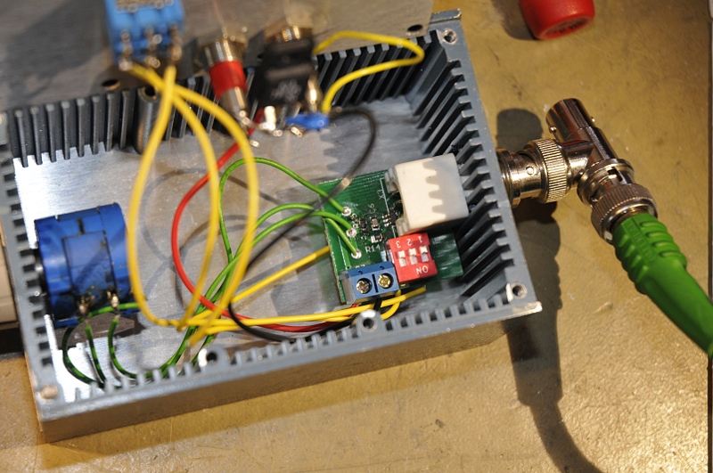
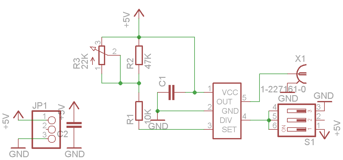
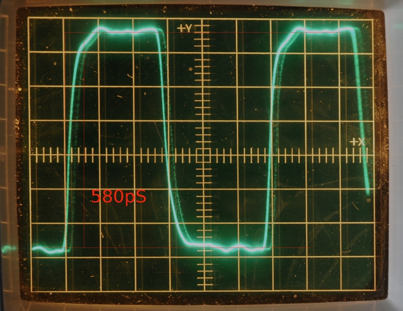
Dit is een mini ICtje wat een complete VCO bevat welke ongeacht de frequentie een stijgtijd van 500pS geeft. Door een 10 slag potmeter is het in drie bereiken instelbaar van 16-160MHz.
Het schema is getekend door Riktw van Circuits online. Hij heeft ook voor mij het printplaatje ontworpen en laten maken.
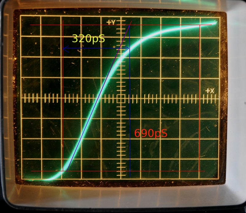
Een meting op een 1 GHz analoge sample scoop: De pulser is hier afgesloten met een 20dB verzwakker op de uitgang en via coax aangesloten op een 50 ohm bnc-GR connector. De tijdbasis is bij de eerste foto 100pS/div. Je ziet dat de puls vroeg afbouwt door demping van de hoogste frequenties. Met een goed compensatie netwerk op de uitgang en een echte RF connector zou de risetime waarschijnlijk nog korter kunnen. Dat is het gele getal als ik de slope doortrek naar wat in theorie zou kunnen.
Update jan 2013
I changed the pulser. It is no fixed at 160Mhz and then diveded by 4. So it runs 40 MHz. The switch and potmeter are removed. I need the fast puls and Tr, niot the adjustable frequency. A fixed 1% metalfilm makes it much more stable. Mount it a bit high above the pcb because it should have a very small paracitic capacitance. According to the datasheet the most stable setting with least jitter. I made a trigger output to it too.
Added a 1K series resistor between pulser and bnc and a 51 Ohm from bnc to ground. The pulser does need a large load. Over the resistor I made a little trimmer for compensation.
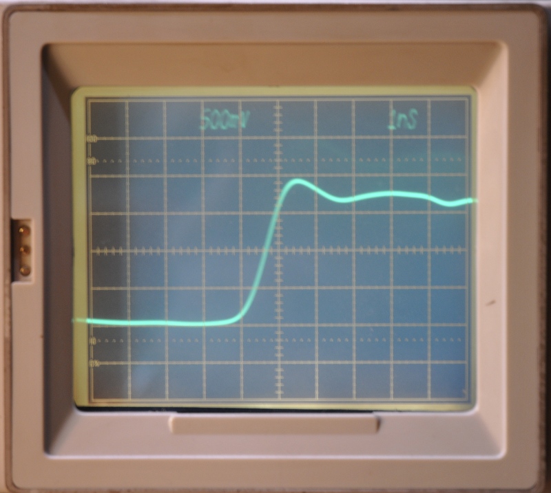
On the Tek 1S2 it now has < 500ps Tr. a little overshoot but for the rest a nice looking squarewave. A big improvement.
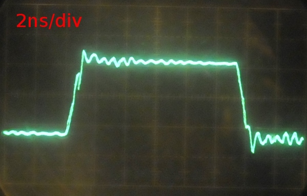
1S2 at 2ns/div 125mV
This is a 5GHz sample scope. You see the ringing here very good.
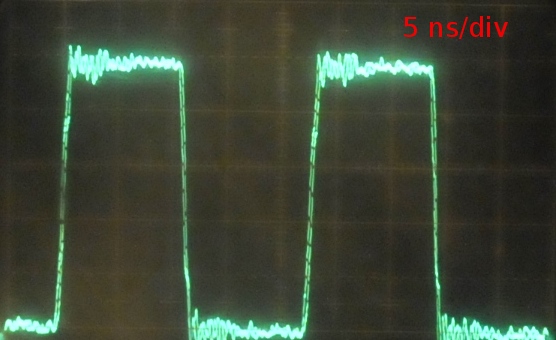
1S2 at 5ns/div
as a compare, the signal at a 1GHz scope
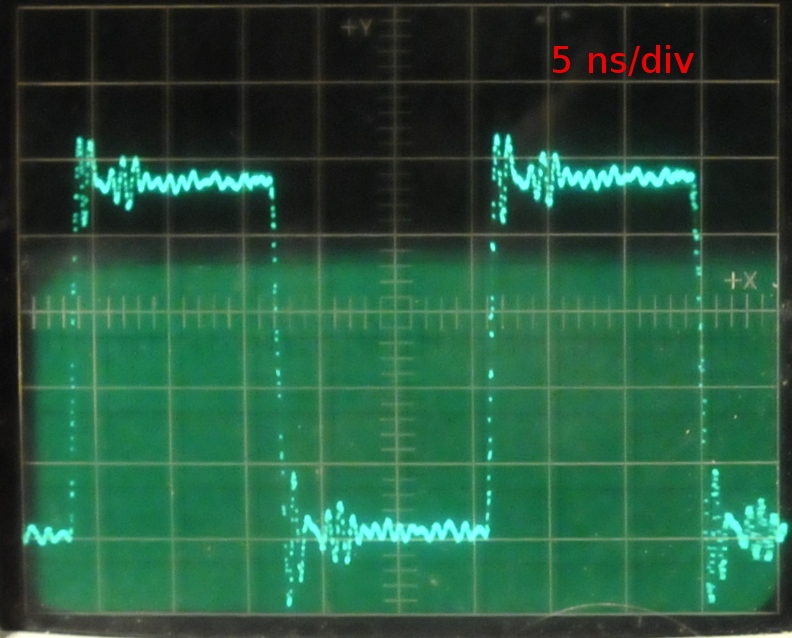
Philips 1GHz scope
At 5ns not much different.
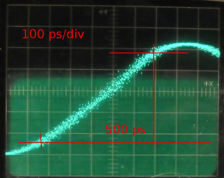
at 100 ps/div
Nice 500 ps curve. But at 5GHz other things show up:
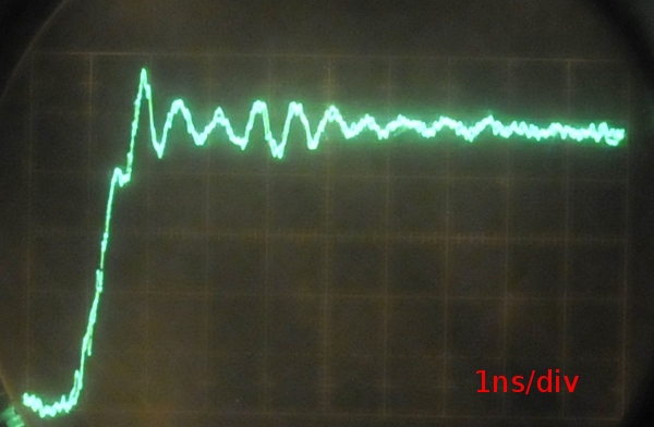
1ns/div at Tek 1S2
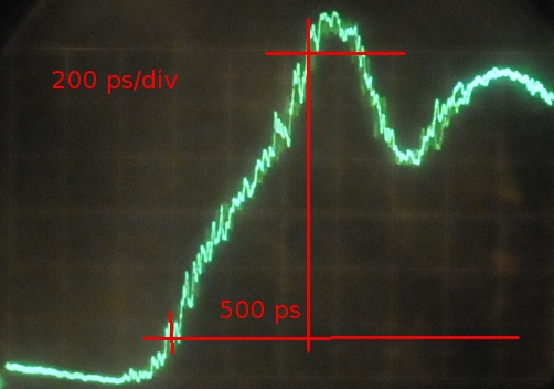
500ps at Tek 1S2, in real better because amplitude is lower.
I measured to the top of overshoot. Whitout the ringing Tr would be under 500ps.
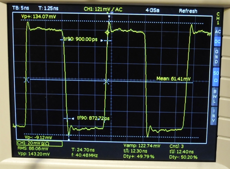
On a 300MHz scoop
This gives a BW between 440MHz (0.4 / 900ps) or 380 MHz (at 0.35 / 900ps) The scope shows still very good details.
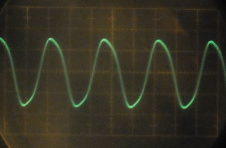
Tek 1A4 50MHz plugin
10ns/div and Tr is about 8ns and this is 50MHz.

