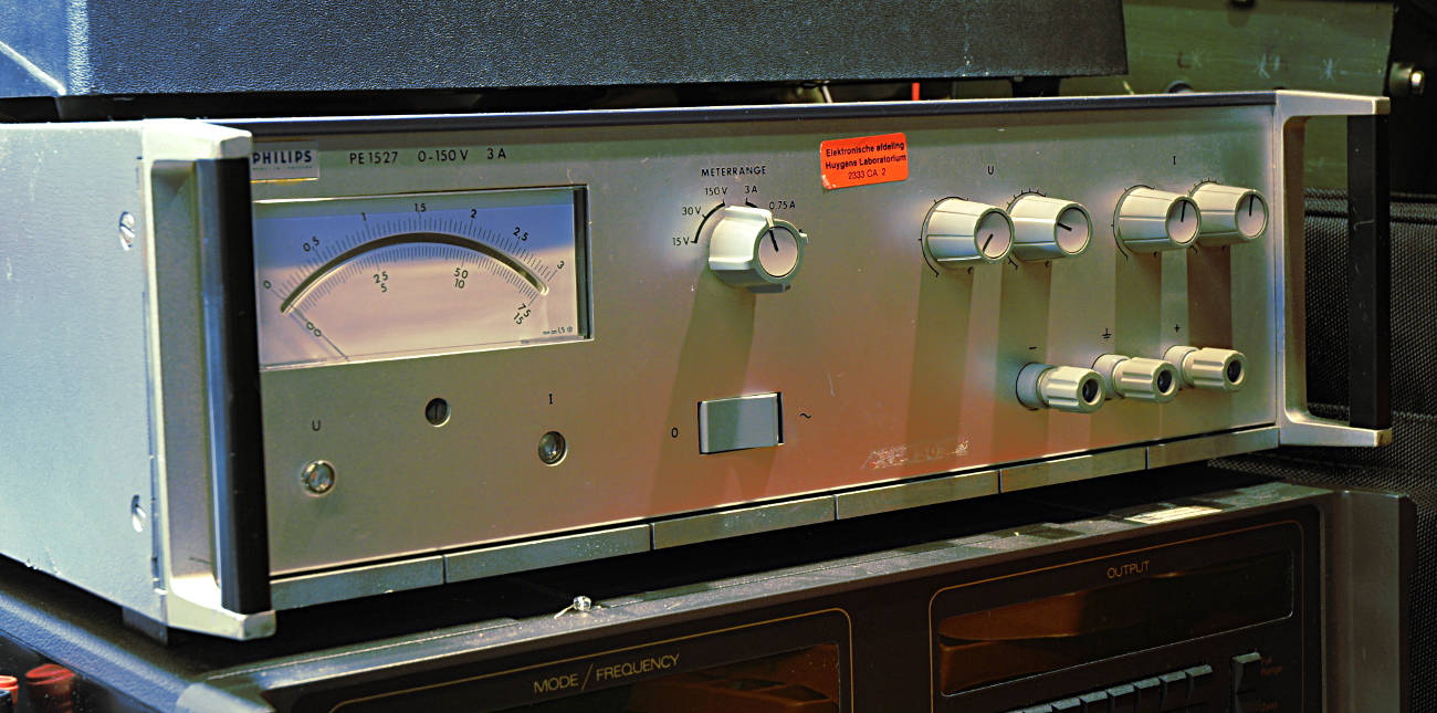
This 27 kilo’s powerhouse is, according the manual, a voltage and current stabilizer.
It can do 3A at 150V. Like modern lab supplies you can use it as a constant voltage or as a constant current source.
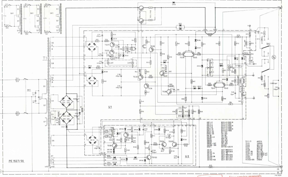
It was not working but I could use a supply like this so I repaired it. That turned out to be a lot of work. I could not find a service manual and when I found one, thanks to a friend, my PSU turned out to be different. It is from 1970 and the manual from 1969 but later supplies are build according the manual so mine must be a very early model. PCB’s are the same but this one uses a total different transformer and preregulator.
Later models us a thyristor (SCR) as preregulator and two windings of the transformer in series to make 150V. The gigantic electrolitics are also in series. The SCR is switched using pulses to keep the voltage of the caps at a certain voltage. It is placed between the caps and the rectifiers. In the DC path
Mine however, has a triac that is placed between the output of the transformer and the rectifier, so in the AC path. The transformer also has two windings for the HV but here in parallel and the three 1800 uF caps are here in parallel too. Also the rectifier part is complete different.
They have to pre-regulate the voltage, not only to lower dissipation in the 3 series regulating transistors, but also because they are -60V types. They are germanium PNP’s. They used both silicium and germanium transistors and diodes. I replaced the 3 germanium power transistors for NOS ones with a higher voltage rating. This because one of them was bad. In a strange way. It started conducting for a while if you knocked on it.
Several other transistors were bad, some leaked to much, some just did nothing, the strange thing was that not a single one was short, the main failure mode of transistors. The most time was spend on finding a bad solder joint between voltage potentiometers and pcb.
The specs of this beast are very good so it was worth repairing. It is very stable, almost like a calibrator, and you can set it with a few mV of resolution.
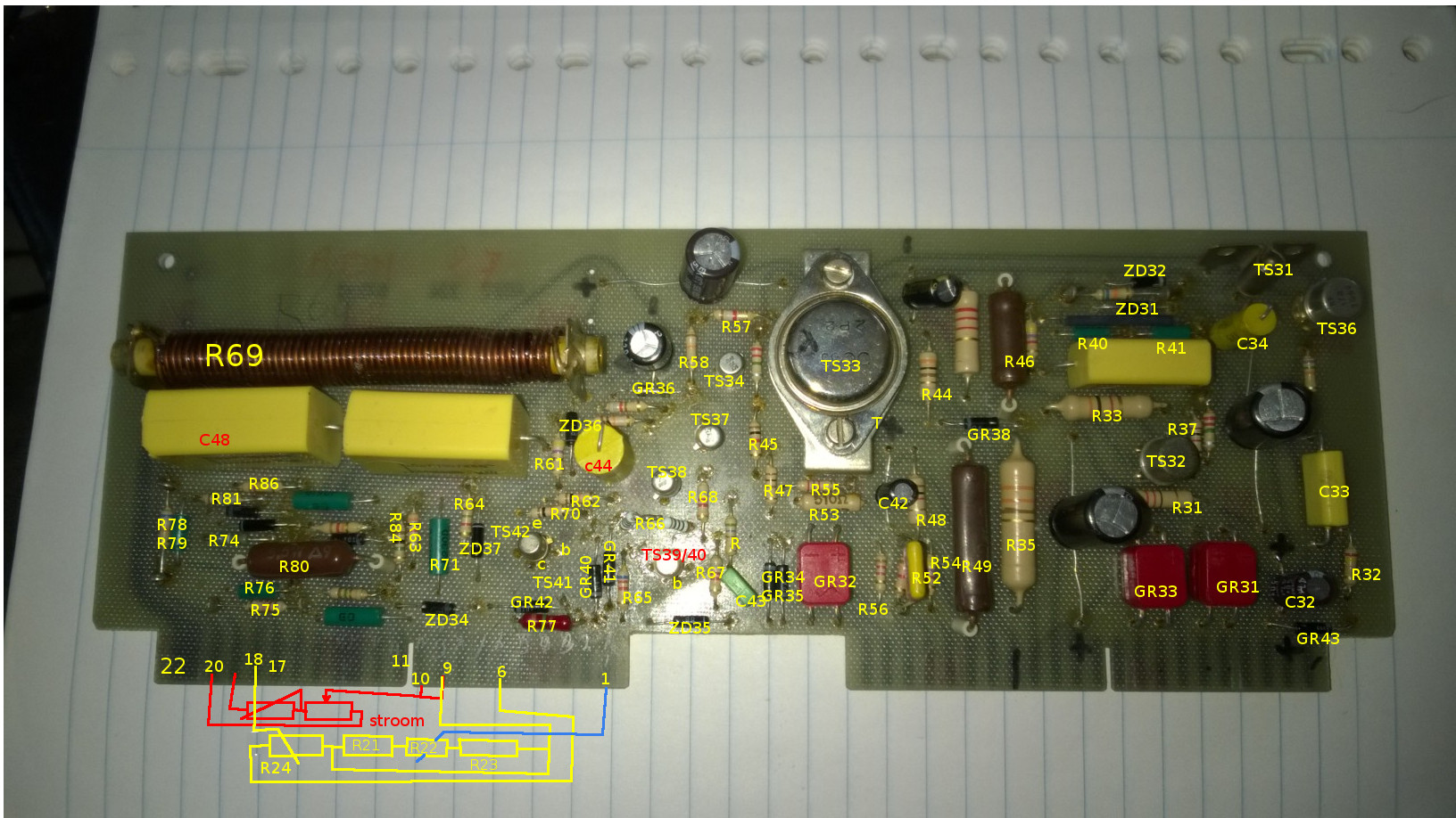
There is no component locator in the manual so I made one for the big pcb.