An LCR meter is a typername for an instrument that is capable of measuring:
- Selfinductance of inductors and transformers
- Capacitance
- Resistance
Some can do more, like conductance, the inverse of resistance.
(G in mho or Siemens).
History
First the base. There are many ways to measure LCR but the most and longest used was the bridge. Still one of the best ways. They are very stable over time and often have a lot of extra functions. But they are huge and difficult to operate. A tutorial: http://www.pa4tim.nl/?p=4298
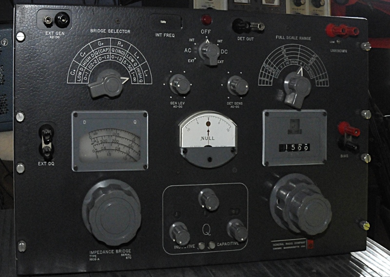
This is the famous General Radio GR1608A LCRG bridge designed by the famous Henry Hall:
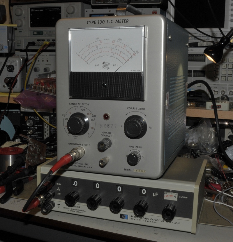
Some bridges use seperate generators and detectors. Some have build in with the option to use external once. An other way was to measure the frequency shift of an oscillator like the Tek 130 down here did.
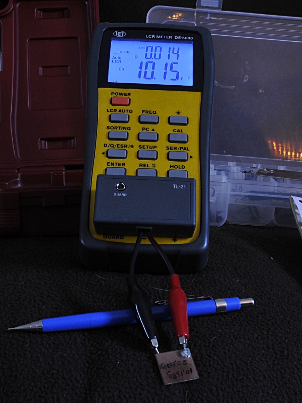
Then came the digital meters. From bench to handheld. Some handhelds are very good ad can do a lot. But bridges are not dead, for instance the GR-1620 bridge is still in production by IET, the former GR bridge department. One of the best handhelds is the IET DE-5000.
Modes
A LCR meter has several functions, ranges and modes..
Capacitance:
A good meter has two modes, Cs, series capacitance and Cp, parallel capacitance. A bit confusing because it is not a real parallel or series thing, it is a model for calculation. You see the model of an electrolytic down here. Cp=Cs if the dissipation factor (so ESR) is very small compared to the reactance (1/(2pifC)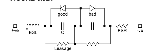
- Elco model
The formulas:
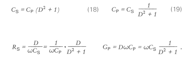
E decent meter will measure D, or DF, the dissipation factor. This way you can correct Cp for R and calculate the datasheet value An example , a 470 uF elco measures 200 uF at 1 kHz and has a D = 1.15. You would say, much to low. So a bad cap.
If the meter reads in Cs there is a problem with the cap. The value printed on the cap is always Cs. But if the meter states Cp it is a different story. If you correct the measurent you get a Cs = 464 uF , only 1,2% low. Nice, so now we still do not know if the cap is OK. But we do know that because we know D, Later more on that. Other problem that only big bridges can deal with is that caps can have big voltage coëfficiënts ( X7R and X5R). So the 10 nF that your meter, made for in circuit measurements gives you at 0,5V can result in a 1nF value if the cap is operated under 12V.
Selfinductance
Here too Ls and Lp. Same as with capacitors. Instead of D we now have Q. Q= 1 / D. Measuring inductance is difficult. The pick up RFI, react on metal objects nearby (eddy currents) and have a current coëfficiënt. With Aircoils you need a bridge like the boonton to measure this but inductors with a magnetic core can change very much. Inductors, like capacitors, change their apparent self inductance with frequency caused by paracitics. So the best way is to measure them on working frequency and test them for saturation.

Resistance
Here some meters offer you AC and DC resistance. AC is very usefull, it is in fact an ESR measurement. Some measure Rs. others measure |Z|. It can be used for things like the Ri of batterie (first read manual, use AC coupling if in doubt)
Other parameters
A LCR meter should give you more parameters. The simple once do not because they measure |Z| or frequency shift and calculate C or L from that. As indicator to know the value from a new good component this is usable. But for faultfinding this is useles.
A cap that has an ESR = 2 Ohm at 1kHz and 100 uF will read 62 uF on such a meter. A simple test, put 100 Ohm in serie with your capacitor and measure again. If the Cs reading changes the meter is junk. .
For capacitance secondairy parameter is D (Dissipation factor , DF) but often also loss angle or phase angle (90 – loss angle) and ESR . If you know one, you can calculate the others.
The series resistance, ESR, is a loss that Dissipates power, so that is why it is called D. This causes a phase shift between Voltage and current. for an ideal cap this is 90 degrees, an ideaal resistor has 0 degrees phase shift. ESR = Xc x D and the phase angle is 90 – arctan D. More:
http://www.pa4tim.nl/?p=3775 about D and ESR.
For self inductance this is Q and Rs. Q = 1/D
Q tells you how low the loss is. Q = Xl / Rs . Measuring Q is not easy because it changes with frequency. So it is , like ESR, not an absolute value you can use on its own.
For (series) Resistance they give you in AC mode as secundairy parameter C or L
G or conductance is something you see on very fewe instrumentsd. It is also called Rp and used for very high resistance. It is the inverse of Ohm. So 1/mho = Ohm. Today we talk about Siemens instead of mho.
Frequency
Standard is 100 or 120 Hz (big coils and caps) and 1 kHz. Datasheets often give the specs at those frequencies. This is because the influence of paracitics is small at these frequencies. For smaller inducters they often offer 10 kHz and on modernj meters 100 kHz is becoming a more and more normal mode. Because switchers work at high frequency you can get an idea how the component hold on higher frequency. It is not because of ESR, datasheets spec |Z| at 100 kHz and D/ESR at 1 kHz or 100 Hz. The most ESR meters read |Z| at 100 kHz but tell you they measure ESR.
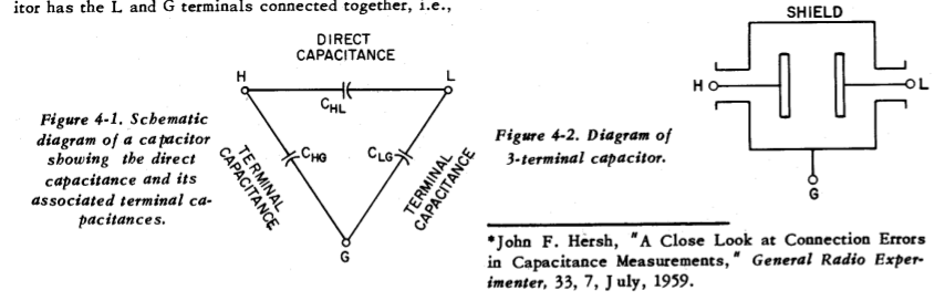
Connections
Very important is the way you connect a DUT, device under test, to the instrument. Simple once use two terminals, or 2 wires. The selfinductance, capacitance and resistance of those influence measurement. Zero will help but is not optimal.
Better is 3 wire. This is 2 wire with an added guarding to shield the sensitive low input of the meter. This lowers paracitic capacitance. It is not just a earthed shield.
4 wire or Kelvin connections are usual for small resistance measurenments. The generator sources its signal to the DUT through two wires and measures the result direct on the DUT over two other wires. This adds inductance and capacitance so for capacitance and inductance they use guarded 4 wire, ( sometimes called 5, or more wire). So be carefull, a LCR with 4 wire needs guarding. Many cheaper/midrange Chibese meter have 4 wire but lack the guarding or use it the wrong way.
Multimeters as C meter
Most multimeters with a C function measure the time constant by applying a DC current and measuring the time it takes to reach a reference voltage. A good one first discharges the cap. If not the dielectric absorbtion causes a measurement fault. This is often not a very accurate way. The principle is not bad but to make it good you need more then is inside a multimeter.
Final
The same things that count for other instruments also count here. Accuracy, stability over time and temp, repeatability, tracebility etc. Most times you get what you pay. These parameters depend on the desing and (expensive) internal references