
As you can see on my site I have a few LCR bridges and they are great to measure LCR. Most are very accurate. % is not always looking great compared to modern LCR meters but they are real “worst case” figures and not made up by marketing. Most serious lab versions are spot on and often stay that for many decades.
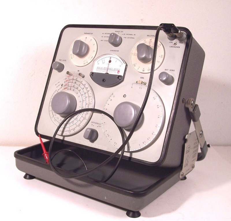
Unfolded beauty
But bridge measurements are not always easy to do. Most bridges have a lot of modes and knobs with obscure readings.
Cs and Cp
First I will tell you about measuring capacitance. There are two modes here, called Cs (series) and Cp (parallel).
A bridge is based on getting a balance. It splits the signal current in two branches. In one is the unknown capacitor, then there are some fixed and variable standards inside. There are many bridge configurations and I will not go in to how they work but tell you how to use them. But you must have a feeling of what is going on inside. The variable parts are switched in other locations for Cs as for Cp. Depending on what you measure the one or other will suit best. This is not the same for all bridges.
Probably the best version, a transformer based ratio bridge
A capacitor has a ESR, the Rs series resistance, and also a parallel resistance. The latter is very high. But together with the reactance they form an impedance. A series impedance can be recalculated to a parallel impedance. Sounds difficult but it has to do with the total current flowing through the impedance. The Rs is very low. Most bridges measure at 1 kHz and small capacitances have a large reactance at that frequency. In that case the Rs is very low in ratio to the reactance. So balancing a bridge will be hard. You need to place a very small R on the other side of the bridge to get balance. So it is more easy to place a resistance parallel. This is what they do in Cp. Now is Cp almost the same as Cp as Rs is very small. But if the capacitor is lossy Cs is not equal to Cp. Today electrolytic caps are much higher in value as 40 years ago and most datasheets from capacitor brands now use 100 or 120 Hz. But it is very easy to transform the values. The capacitance is most times more or less the same and DF is simply 10 times higher at 1kHz then at 100 Hz.
The value given by manufacturers is allways Cs so when you measure Cp you need to do some math too ( also in case of a digital LCR meter)
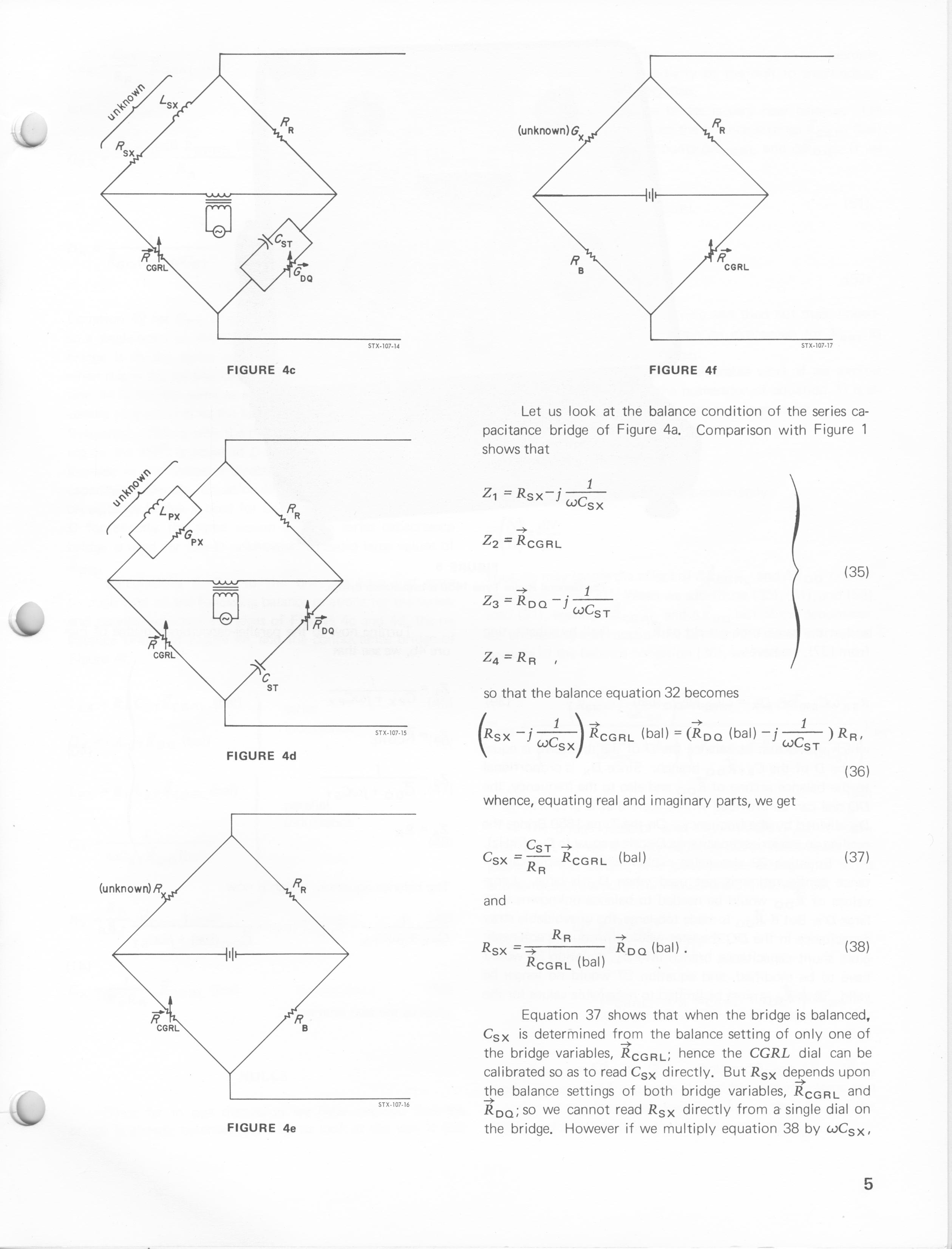
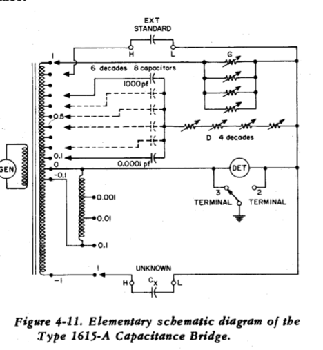
some configurations
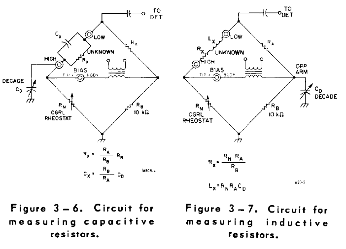
How to do that is easy with the formula’s below:
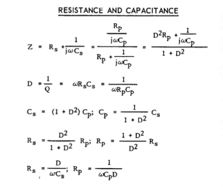
Formulas from the very educational GR1650B manual.
Finding the sweetspot
But first you need to find that balance. For that you have 2 knobs on most bridges. One is called D ( or Q, Q is 1/D) and one is C.
On some special bridges they use G, that is 1/R in mho ( or more modern Siemens)
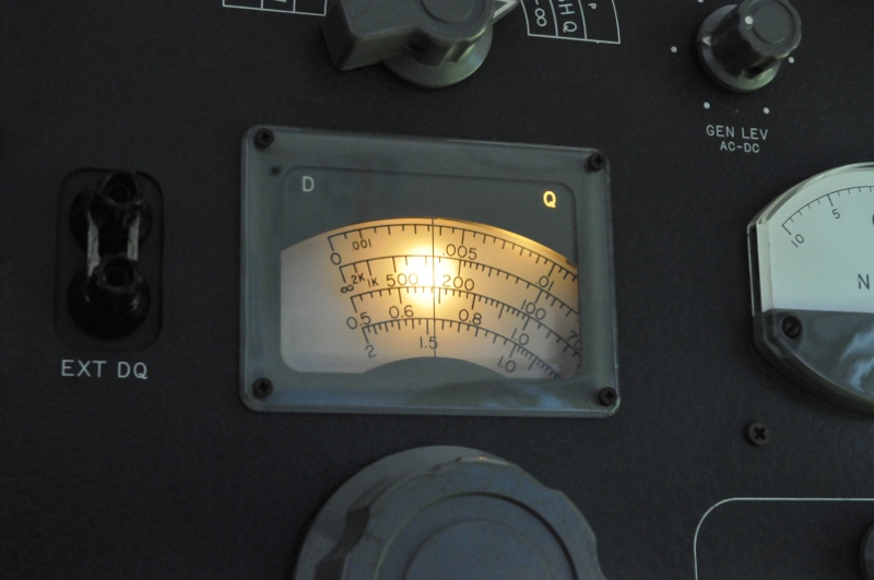
A lamp behind every scale, so you see the one you have to read
Most bridges use a sliding zero, the balance point is zero. And the meter ( internal or external, sometimes they use a headphones) is a null-detector. If the current through both legs of the bridge is equal and there is balance the bridge is at zero. There are also auto and digital bridges that look like a “normal” LCR meter.
This is the most difficult part because D and C influence each other. You need to adjust first C until the meter dips a bit, then adjust D until the dip is sharper, then C again to get it even more sharp and then again D for an even more sharp dip and every time the meters gets closer to zero. You can not allways get to zero for very small capacitors because the noise and very high impedance. But you look for the sharpest dip, the one that will give a deflection reaction even when looking at the knob 😉
After balance we have two values, Cs ( or Cp) and D. D for Cs is the same as for Cp. D is the ratio between Rs and Xc so if you know D you can easy transform Cp to Cs and vise versa like you see in the formulas above.
Wat je eigenlijk meet
But this value is the value of Cx including the capacitance and resistance from the bridge terminals and clips you use. So we also measure C without a capacitor attached. D will be as good zero in that case. Only a few bridges can measure that residu. That value of C must be subtracted from the measured Cx to finaly get the real Cs.
Moste bridges can measure Rs in AC mode to. You can use that to measure the Rs of the clips and terminals and subtract that from Rs. Now you have the true value.
Most of those bridges can also measure the ESR direct using that mode but zeroing will be hard because the reactance part. Some bridges like the GR1650 or 1608 have a posibility to connect an external capacitor to one part of the leg to balance the bridge this way. This works like the D dial. The manual will tell you how because this needs some math to correct for the right values. But this is a tutorial about using a bridge for beginners so I will not go in detail for all the other thing you can do with a bridge.
Extrenal capacitor
Most important is practice and getting a feeling for it. The result is a rather quick operation that will tell you the state and value of a capacitor. You can calculate ESR from it, phase angle ect but D tells it all. See my page about ESR for that. But in short. A perfect capacitor has zero ESR and in that case D is zero. A very bad cap has a high ESR and D will be very high. Datasheets always state D and the frequency but often they name it DF or tan-d.
An ESR measured with an ESR meter of 1 Ohm does not tell you anything. But if that is measured with a D and that 1 Ohm is D= 0.01 you know it is a very good ESR, if D is 10 you know that ESR is from a very bad cap. For your ESR meter you can calculate Xc from the capacitance and frequency. Then do ESR / Xc and you have D. And now you know if it is a good or bad ESR. For electrolytic caps a D < 0.25 at 1kHz is most times good, 0.25 to 0.5 can be good, above 0.5 it becomes critical, above 1 it is just plain bad. Datasheets will tell you the max value of D. This is related to the max working voltage. Often they give a value per Voltage under 1000uF and a correction factor for higher capacitance.
Big caps
There is a downside, most bridges stop at 100 or 1000 uF capacitors. But that is not a real problem. Just take a good, well known low ESR capacitor that your bridge is able to measure and then place this in series with the unknown capacitor. As you know: 1/Ctotal -1/Cknown=1/Cunknown. Then subtract the known cap Rs from the measured Rs to get the unknown Rs. This still will give you very accurate results.