
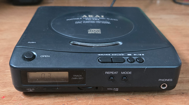
This is a very cute portable CD-player made, if I’m correct, in 1992. After years of for most commercial repair I wanted to do some fun stuff in between. No hurry, no need to succeed, just relaxing repairs.
I volunteer at the Salvation Army thrift-store and this beauty landed on my desk to test before it went in the store. Sadly it did not work so I took it home to see if I could repair it. I seldom repair consumer stuff so a CD player was a new one. There is no service manual but the inside is for most Sony so I did some searching and the optical unit was the KSS-220A from Sony and the main IC’s too. They both are used in the Sony D99 Discman. And I found a service manual from that player.
First I started reading about how CD players work. That is very interesting. In short the laser needs the right current. The IR beam it makes goes via a mirror through a lens to the disc. That lens has two “servos” made out of a coil and a magnet. They move the lens from left to right to track and up/down to focus. The light reflects back to a sensor that is made from 6 photo-diodes. 4 are for focus, 2 for tracking. They are named A, B, C, D, E and F. They are housed in an 6 pin IC on the optical unit.
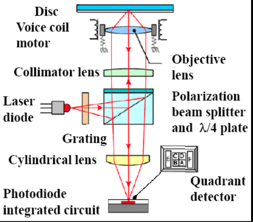
Source: https://www.researchgate.net/figure/Optical-structure-of-a-DVD-pickup-head-see-online-version-for-colours_fig3_283434048
E and F are tracking, A to D for focus, if there is more light on E or F the laser is tracking wrong, if the light on the 4 focus sensors is not correct the signal is out of focus.
There are some potentiometers on the board to adjust things. In the Akai, I reverse engineered the part around the main IC’s and now know the function of each potmeter.
R505 is for the VCO/PLL, the VCO seams to run at 8.65MHz (I did not use a counter but just the scope so it could be 8.70). It did not looked locked but I left it alone for now because the Sony SM stated 4.35MHz so the Akai seems to run at the double frequency. A501 is focus gain, A502 is Tracking gain. Sony states not to align them. A503 is tracking balans. There is no focus bias potmeter. It is fixed by 3 resistors in series between 3,75V and gnd (22k, 15k, 11k) The problem is that the align data stated by Sony are way of and without the correct data I left them alone. I only adjusted tracking balans a little but this pot is extreme sensitive.
The Sony IC’s:
A1271Q is the RF amp,
CXA1272 is the Focus tracking, sled/clv servo controller
MPC1715FB is a DC/DC converter controller
In the D99 manual there is a pin desciption for these IC’s and the optical unit.
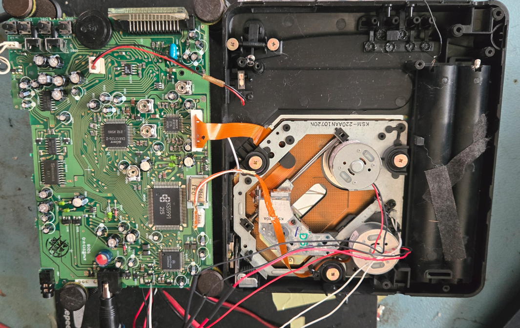
But first I had to repair it. It powered on, sometimes played a few seconds and then stopped. So I opened it. And the fault was found fast. The 4 trace flexcable was almost broken in 2 because the cable is mounted in a way that it folds back. Unneeded because if they had mounted the wires 180 degrees this would not had been necessary. It looks like it is in a connector but it is not. You have to desolder it.
So first step was to fix the cable. It is 3mm wide so that was fun.
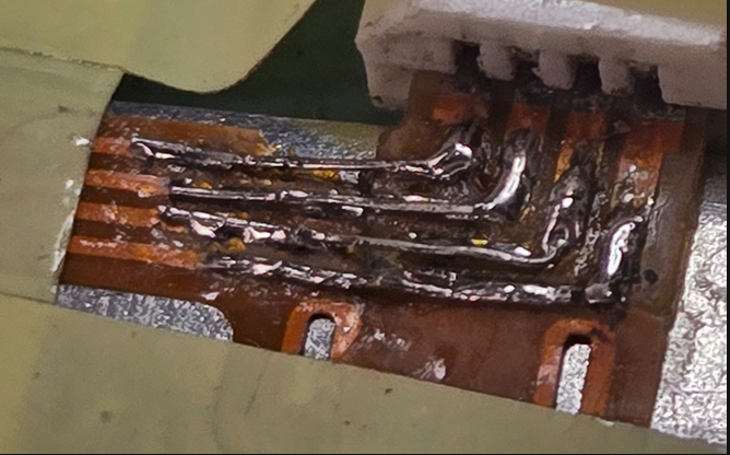
First scratch of the plastic. Then solder some strands from a wire onto the traces.
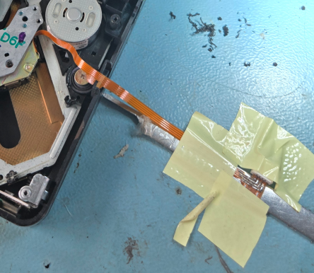
I taped it to the table to hold it in place. And to enhance the fun after I put everything together and tried it, still no succes. Turned out the flex had come loose from the guides and caught in to the hinge. It was almost cut in 2. Fixed that too, closed everything, tried again and still no activity. Opened it up again. Due to the folding back the cable broke again just next to the first broken piece. So I added a few cm of cable by soldering 4 very thin wires. And to make repair and adjusting more easy I made the long black, white and red wires about 15cm longer so I could work on component side of the board too. (3 images up). Finally the optical unit reacted. But it skipped constantly, like every few seconds.
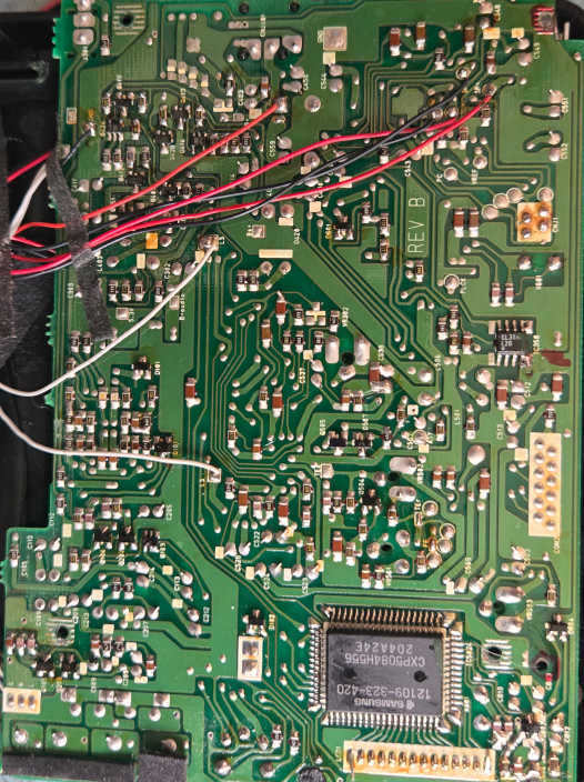
Here you see where the wires are attached in case yours came loose.
Now everything was ready for aligning. But sadly, the measured values were so way off that I did not dare to change them or I measured wrong. One reason could be Sony used 3.4V for the IC’s but Akai used a not adjustable 3,75V. The eye-diagram (pin 14 from the MPC1271) had some more jitter then I liked but the potentiometer for the laserdiode bias was in an impossible to reach place and I did not want to risk damaging the diode by to much current.
I wish I had the correct data so I could have adjusted the player. I only dared to adjust the tracking and now it plays nice but every few minutes it stops for a few seconds before playing on. Looking at the mechanism I think it is a tracking error or the fact I now used nimh batteries. On the workbench open it played fine without the pauses but powered by a labsupply.
I learned from some video’s that the best way to make a CD player useless is to make adjustments without the correct data. I will study some more to see if I can come up with the data my self but first make a 12 to 9V psu (I live since 2022 on a boat and power everything from my 12V net if possible (except my workbench, that runs on 230V). And if it than still has the pauses I think I will try to adjust things just by trying. (I then note the pot-loper positions.)
Update: it stopped working more and more. Turned out the PLL unlocked. The PLL is there to sync the rpm of the disc with the VCO and so clock that runs the electronics. Measuring with the scope showed the VCO running correct or suddenly way to fast (8-10MHz). Then it stopped and every now and then only gives a burst. I do not know if it’s a dead 1271 because that has a clock input from the smps IC that runs the two motors and there is no clock signal there either. The 1271 can have a short to ground or the smps has a fault or I’m chasing a red hearing. I will search on for info and look if I can find a few dead CD players that use the sony chipset for a transplant as test.
Update 2:
There is a Samsung KS5991 inside, a digital signal processor. It runs on a 16.934,4MHz Xtal.
The problem is all frequencies at the pins of that IC are to high and this IC makes the VCO for the Sony IC’s. Turns out the processor Xtal runs at 16.945,5MHz. That is 11.1kHz to fast. This causes all other frequencies running to fast and that is why the PLL does not lock. Now I have to decide if I will search for the right Xtal because I am not sure if this is the only problem. (and then there are the brittle flex-cables).
Update 3:
I used a RF generator instead of the Xtal but the PLL will still not lock. I think that IC is partly dead. Maybe one day I find a good IC and Xtal but for now I stop this project. I repaired 2 Sony Walkman CD players and those work now fine so I will use those to play my CD’s on board of my boat (No space for a full size CD player and I feed the Sony’s from my 12V boardnet using a voltage regulator.