A friend gave me an old transmitting compass. A Neco Marine NM3. It was long ago part of a ship’s autopilot. The construction is interesting. A flux-gate is very sensitive in measuring magnetic fields. But the earth magnetic field strength is very low. You can amplify the signals and make a compass that is only a flux-gate but that will need a lot of filtering too. So they came up with a sort of a hybride. Above the flux-gate there is a normal magnetic compass. A magnetic compass has a magnetic needle and that magnet has a force much higher than the earths own magnetic field. So they measure the location of the magnetic needle.
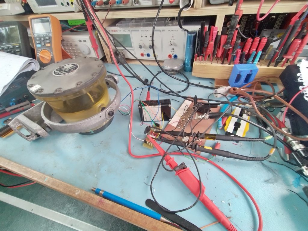
The jar at the left is the compass. It is filled with some oil and you see the white line of the needle floating in the oil. The unit is mounted in cardanisch mount. Under the needle disk you see a non-transparent part of the jar. That is the Fluxgate. There is no ferro-magnetic metal in the whole construction. The screws are copper, the mount aluminium. The dark disk at the bottom is pure copper and only serves as a weight to keep the jar in this straight up position.
The flux-gate itself is made of 4 coils. 1 drive and 3 sense coils. The drive coil is driven by a 400 Hz AC signal and is a toroid. The sense coils are winded over the toroid, each 120 degrees apart. Small deviations in the magnetic field cause changes in the output of the sense coils. By watching the output of those coils it is possible to detect the position. If the magnet is exact over a sense coil the output is zero. The other 2 are in some in between state. Bij measuring the amplitude of the coils and polarity, you can calculate the position. At the zero output position there happens an180 degrees phase jump. The signal switches from positive to negative or vv.
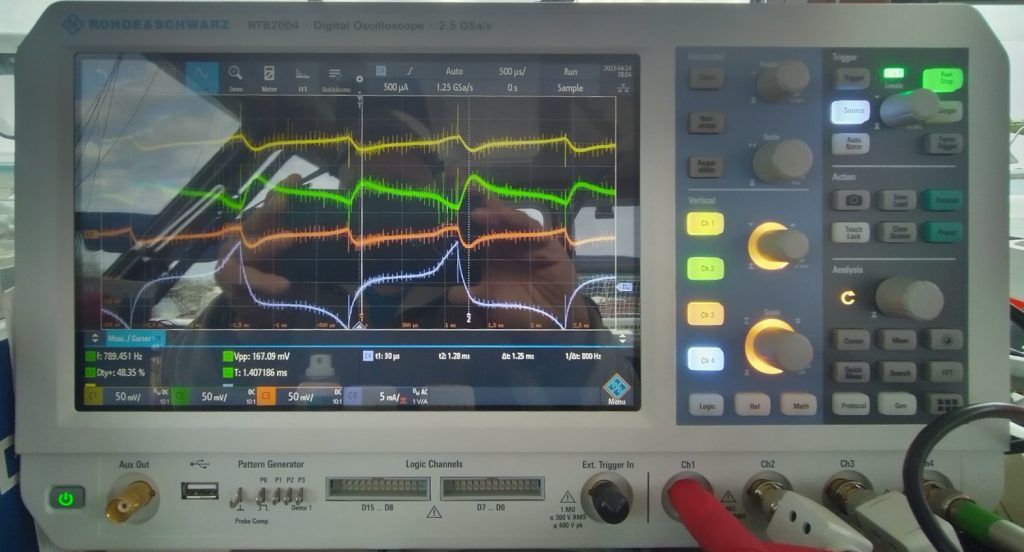
The drive coil must be exited in such a way is goes in and out saturation. That seems harder then it is. Just crank up the signal until you see signals out of the sense coils. I used a sinewave. The original autopilot uses a different detection methode. It has 4 coils in the control unit too. 3 of them connected to the 3 sense coils and one that has a capacitor in parallel to make it resonant. Is is called a resolver. I wanted a compass so I have terminated the 3 outputs with some RC filters. This way I get the “sawtooth” like response. The white trace is the current through drive signal picked up with a current probe. The signal is only a few mA. The other traces are the sense coils.
Here you see what happens if you rotate the unit (and the ship it is mounted to). The green line goes to zero. The yellow trace is positive, de orange trace is negative. If I rotate it more the green trace will go negative. It is very smooth. It notes the smallest rotation. You can easy get a 1 degree resolution with it.
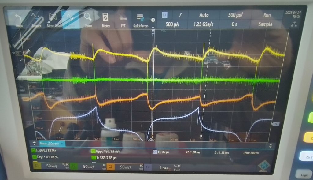
The traces look nice but that it thanks to the filters. You can see all the small “needles” on the traces. Without a filter they are very large (like 2 divisions).
The next step is to make a driving source. I now use a function generator. I have not yet decided what I will use as a compass indicator. I can go the digital or the analog way.