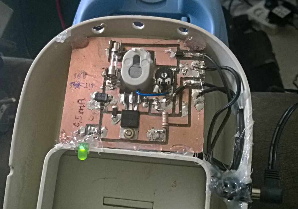
We have a “Kruimeldief”, a battery-powered vacuum cleaner. It was previously unusable because the batteries would no longer feed it. The original adapter was a 15V AC adapter and in the kruimeldief there was a diode. It has a battery pack with 6 C-size nicd cells. Two cells were dead. I changed the two cells for two good ones from my junk box, made in the 1980s but still going strong.
I charged them with a lab power supply as a test, and then I tested them in the sucker and it worked as it should. But I did not like the “charging system”, so I trew a few parts from the junkbox together , sacrificed some frozen virgins and soldered it under a full moon, the result was this schematic:
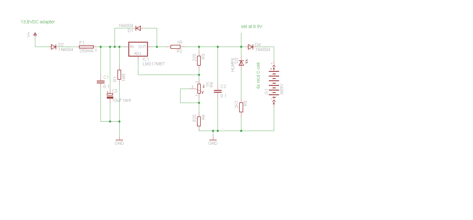
Adjust the output from the LM317 to 8,9V. The battery voltage rises while it is being charged until the voltage is almost as high as the output of the charger. I adjusted it for a 10mA trickle charge. The LED is there to load the 317 and as an indicator to see if the adapter has power. The diode at the output is there to prevent the battery gets discharged through the LED. The diode on the input is for protection in case someone plugs in the wrong polarized adapter. The diode over the 317 is standard protection.
Only a small thing, when you want to measure the voltage after the output diode without the batteries , there is a chance you get the wrong value. A diode conducts only if there is enough forward current. The 10M resistance of a DMM is often just enough, but many high-end benchmeters are > 1GOhm in the 10V range. In that case, something like a 100k resistor connected as a load if you want to set the maximum voltage on the battery. Another thing, the Vf voltage drop across the diode is approximately 0,65V. But that is not a fixed value for all of diodes and also a result from the current through it.
But it is not very critical in this arrangement. The 317 can deliver 1,5A, The serie resistor limits the max current. This is a mix of CV and CC and the idea comes from an LM317 appnote. Normally, you only use of a series resistance between the Vout and adjust and do not care about the voltage. The current is then near 1,25V / Rserie. But in that case the battereies get charged too much if you do not disconnect the battery charger and if you have input voltage limitation for the LM317 , the voltage gets too low (it should be about 2.5 V more on its input then output.)
The LM317 works on a simple principle. It will change the voltage between the adjust and V-out pin until it is 1,25V. In the default situation, there is a 240 ohm (220, but also works) resistance between the 2 pins. You can change the current flowing trough the 240 ohm by adding a resistor from adjust to ground. You then have a voltage divider. The LM317 is changing its output voltage until 1,25V drop over 240 ohms. If the value of the resistance to ground changes, the current through the voltage divider changes and this leads to a output voltage change.
In the charger above, the voltage divider is fixed (after setting it on the desired “almost no load” value). But the current through the resistor increases the voltdrop over the 220 ohm. The 1 ohm is part of the voltage divider. So the 317 will change the output voltage until the volt drop across the 1R and 220R is 1,25V again. This way there is a relation between voltage and current. You want to know that relation ? Then do the math 🙂