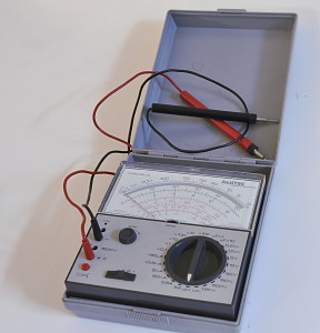
I got this meter from my dear friend Rene. It was a bit dead but I was curious how it would work so we fixed it right away. The biggest problem was the damage from leaking batteries. The contact where green but I sanded them and after that tinned them. Besides that a transistor was dead.
It was made in three versions. The basemodel , the S version that has the electronic overload protector and the US that has the protection and an Universal Signal Injector. I found a price of fl. 217,= for the S version in a Dutch magazine from 1978
Besides two pF ranges it has x0.1 to x10k resistance ranges. Current goes from 50uA to 5A. AC and DC. The resettable fuse is a nice safety feature while measuring current. Voltage goes from 0,5V full scale to 1500V. The x0,1 ohm and 0,5V ranges are rare on analog meters. They also made a kV probe.
The meter movement is a class 1 moving coil meter with center magnet and shockproof jewel mounts and protection diodes. Accuracy for DC is 2% for DC and 2,5%c for AC and resistance. The sensitivity is 20kOhm/V. It measures AC from 20Hz to 20kHz (sinewave).
Like more meters from that periode it can measure capacitance. It needs a special cable for this. That plugs into the side of the meter to connect the meter to 230VAC. It has two ranges, 0-50nF an 0-500nF. It must be set on AC and one of the two pF ranges. Then short the probes and use the zero ohm potmeter to set the needle full scale. Then you can measure. It measures the reactance from the capacitor but shows it scaled to pF. For bigger capacitance they advise the ballistic methode. There you use the resistance mode and note the highest value the needle reaches. Then you use a tabel in the manual to convert this to capacitance. I do not have that cable but tried it with a bit improvisation and it works.
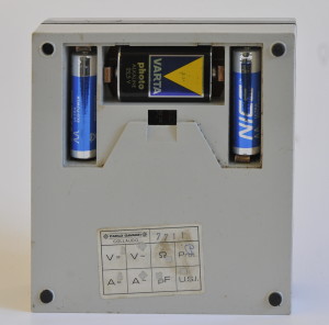
It is a passive meter but has some active electronic circuits. It is powered by two 1,5V A-cells and a 22,5V battery (ever ready B122). The A-cells are for resistance measurements. To check them you turn the zero resistance pot. If you can get the needle beyond zero in the x 1 and x 10k ranges all the batteries are OK.
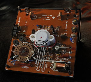
It has a function that is a bit unusual for multimeters. The function is named U.S.I. It is made from two transistors and two transformers. It should generate a 20Vpp 500kHz signal that is modulated with 1kHz and so much harmonics that they can be detected upto 500 MHz. It draws 25mA. I must check mine because it generates a 1,2kHz, 13Vpp 10%DC pulse. The meter movement does nothing in that position. The AF126 transistor from this circuit was dead.
An other strange thing is a “connector” at the left side in the picture above. It is made from some thick yellow copper parts. It is the connector for the 230VAC input needed for the capacitance range.
The meter has two nice probes with very cute looking 4mm plugs. The red probe has a 5A 5x20mm fuse. An other nice feature is the reset-able “fuse” in the meter. That is the red button in the left hand corner on the front. It has an amplifier that measures the voltage over the meter movement. If it is 8x to high the electromecanical latch trips and disconnects the meter movement after about 7ms for DC and 7-15ms for AC. It uses the 22,5V battery to feed the circuit (the battery voltage must be higher as 19VDC. The x 10kohm range uses this battery too.
After repair and cleaning I calibrated and adjusted it. The result is above expectation. It is now spot-on and very lineair. My best analog meter regarding accuracy and usability.
Here you see the 22,5V battery. The varta had not leaked and still was 22V.


