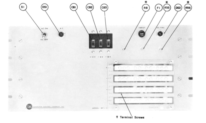
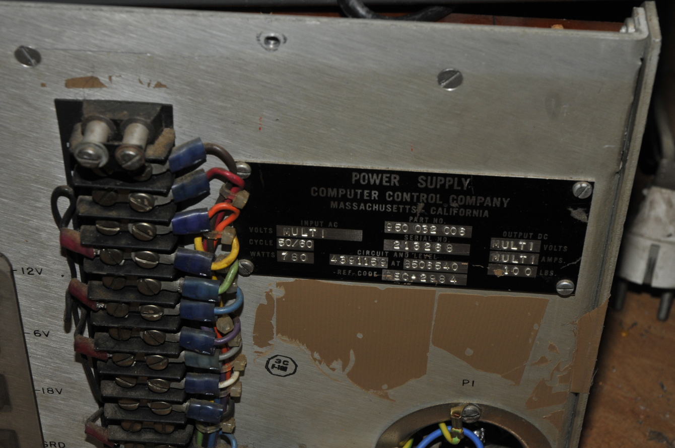
This is a RP-32e, almost 50 kilo, power-supply from a 1964 DDP24 mini computer made by the Computer Control Company. It is not a looker if you watch the front. Just a plate massive aluminium, 3 autofuses , a “normal” fuse , a powerswitch and 4 nickeled copperbars with a lot of mountingscrews that was used to connect it to the computer. The computer housed 2 of these supply’s. (and some other supply’s too).
This is what they meant back then if they talk about a general purpose mini computer.
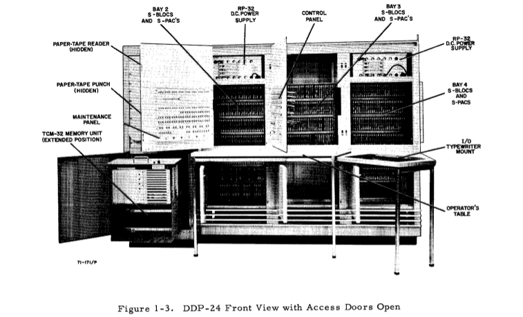
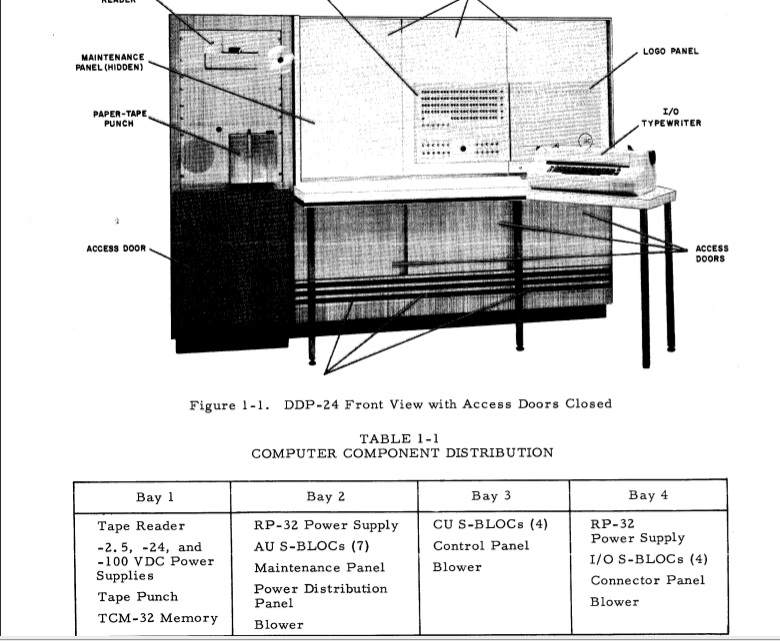
The power supply’s are mounted in the top of the computer. I feel sorry for the tech that had to work on/in them. If they dropped it, it probably went straight to the basement, taking a shortcut through the floor.
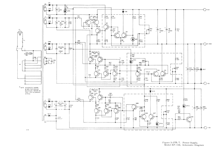
To my surprise I found a few manuals that included the schematics. There are 3 outputs. Two of them are stacked. -6, -18V, beside those it has a +12V. The 12V is only a few amps. The other two are 20A and can be used floating to give +12V at 20A.
The former owner only soldered some wires to the pins from the mains connector. and covered it with the tape you use on a cardboard box. I removed the old chassis-part and milled a plate that now holds a modern connector.
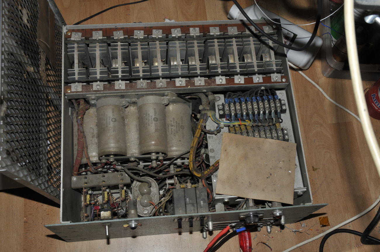
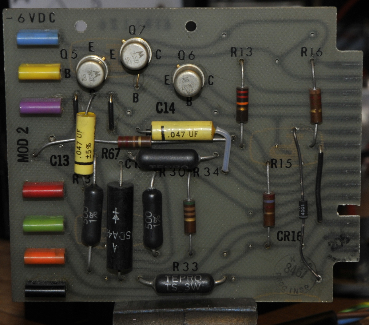
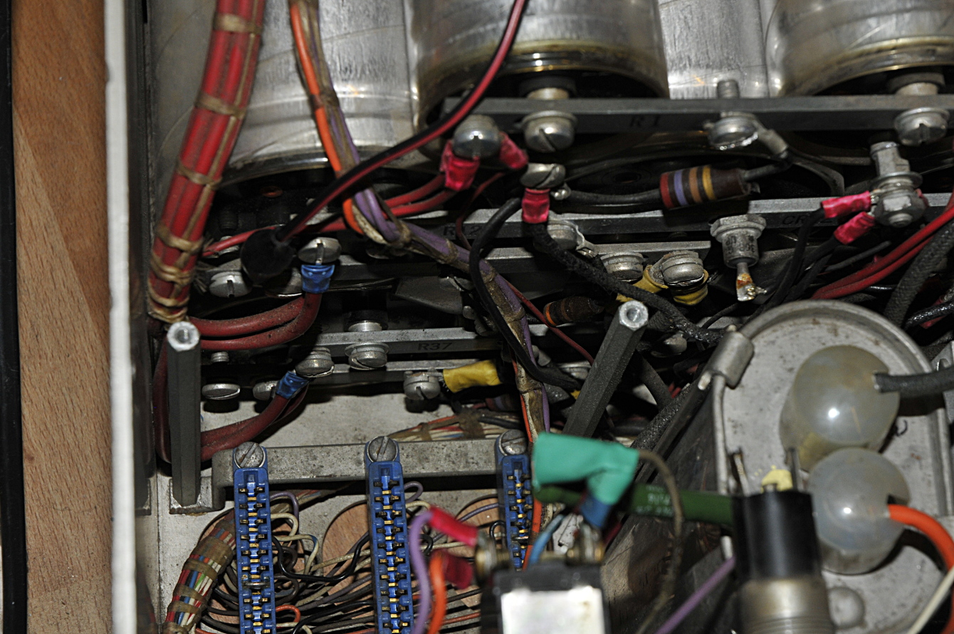
The way they build it was no expense spared. The power transistors and diodes are mounted on plug-able units. And so are the 3 regulator circuits.
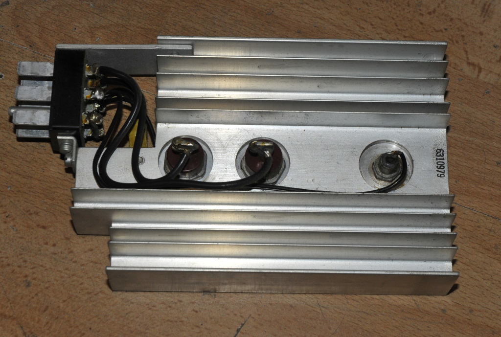
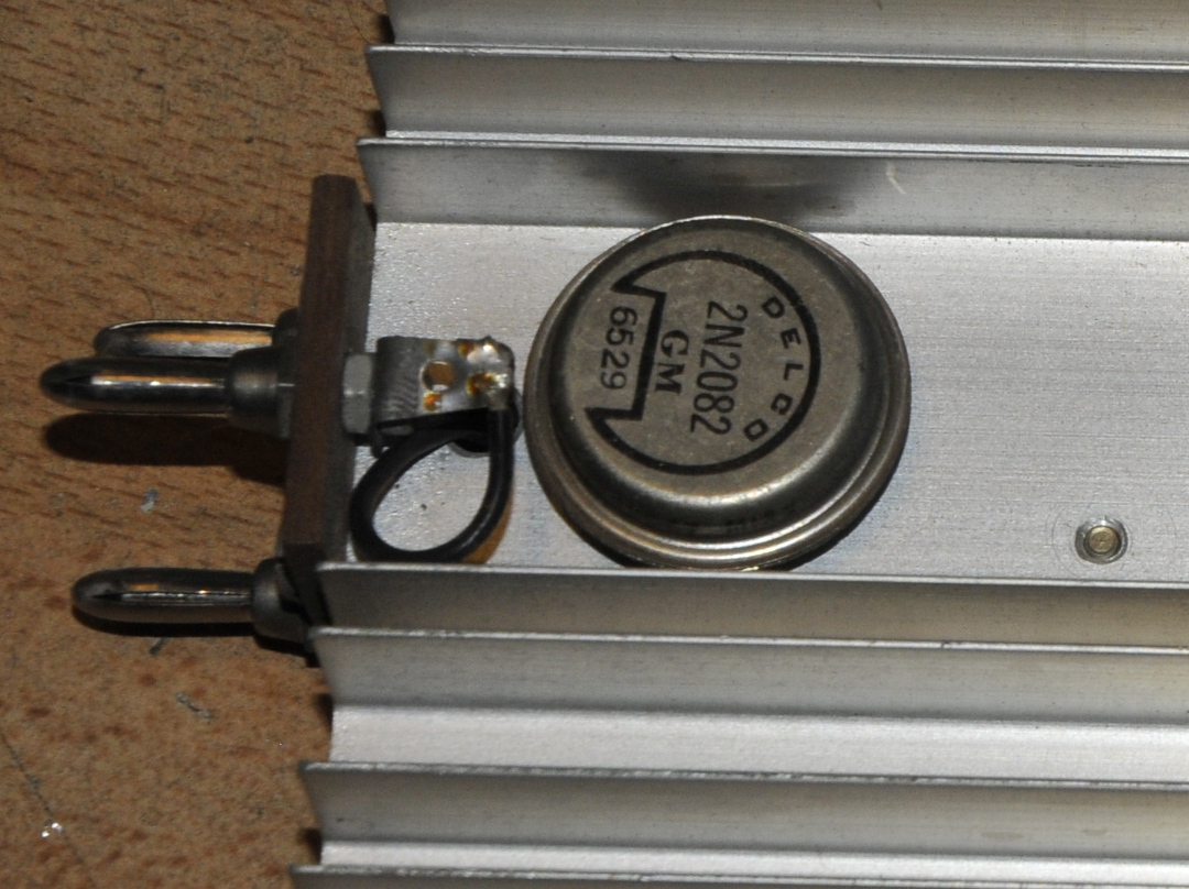
Two power transistors and a diode on a plug-able heat-sink.
The colored things to the left are multimeter testpoints.
The transistors are Germanium. This powersupply was working fine but I had not used it for years and never opened it. But now I needed a lot of amps to test something so a nice excuse to look inside. The capacitors are enormous. They must have cost a fortune in the sixties. Not only in size but also in capacitance. They are 42000 and 11000 uF a piece. They are connected through copper bars.
The power switch did not work. The 3 separate switches I used to power it on turned out to be autofuses. So I opened the switch and gave it some TLC. For those who now are thinking that I must be crazy to repair a switch. You are right, why ? because I can 🙂
These things are beautiful made and I’m sure it will outlast a modern switch. The problem was just some dried grease that popped the spring of position so it was an easy fix. They used scary thin wires for the 230V (and all the other wires) A bit of a surprise after looking at the massive copper bars on the front and rear. It has one 230V fuse. It is huge, like the HRC fuses in a multimeter. This fuse is a combination of a normal fuse and a thermal fuse. The endcaps are goldplated. The high-end audiofans would probably pay a small fortune for such a nice fuse.
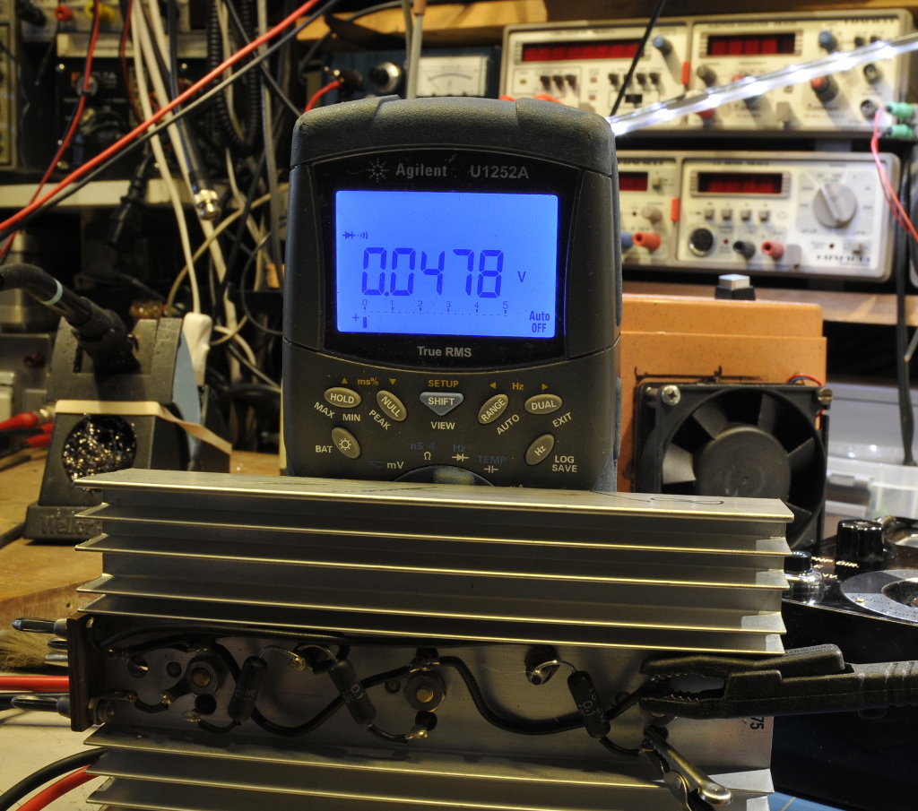
Because germanium transistors often forget they are semi-conductors instead of conductors and they are used in parallel, it seemed a good idea to check them. First the diodetest of a multimeter. Simple and often all you need to know. But as you see on the meter above, it is almost a dead short. So maybe one is short. But after removing and testing a few, they all gave the same result. I had a few (also used) in my stock so I tested those. Same result. Time for a more serious test. A nice excuse to play with my beautiful Metrix transistor tester. The Peak atlas component tester had no clue about what I tried to feed her.
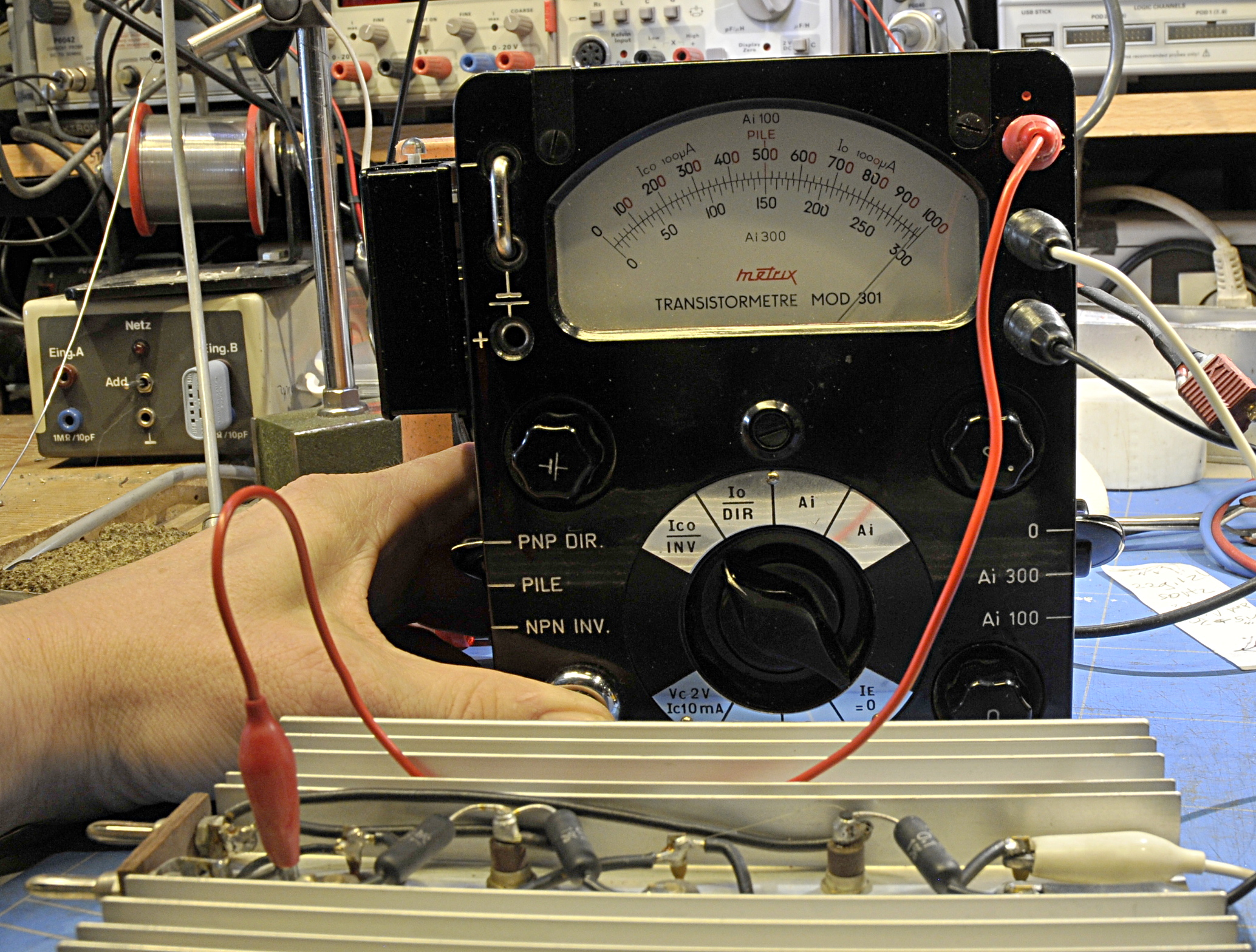
Here you see the Ico leaktest. It swings full scale. That is 100uA. The Io test gave 1mA leakage. So you would think they must be dead. But in that case they have no gain. And that was not true. It had some gain but it was almost impossible to zero the Ic function. this must be done before every measurement. So what was going on ? It did not look like it was caused by tin-whiskers.
But there is a way to test them and be 100% sure. Time to call the mighty curve tracer.
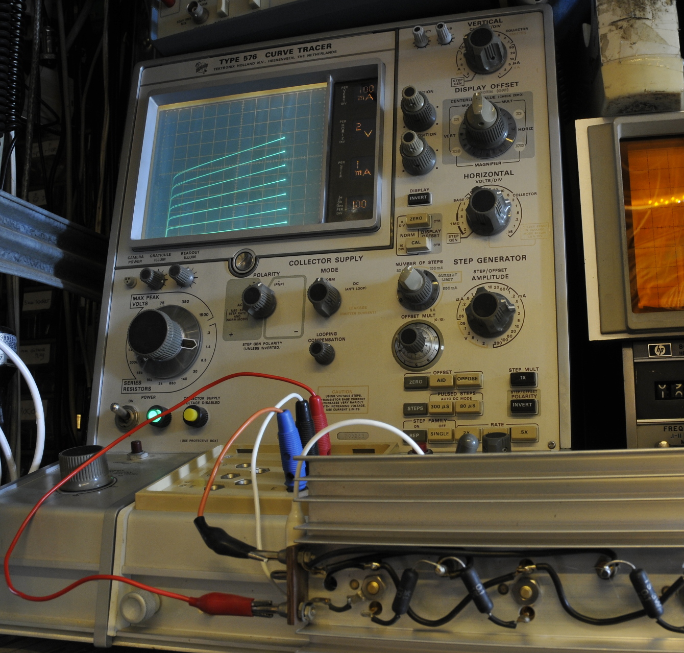
The transistors are indeed leaky but that 100uA is peanuts compared tot the base current it uses to operate. I could not find a datasheet at that time so I was a bit carefull. But the data I found later, talks about 200uA Icbo and 2A operating base-current. On the picture it pulls around 7 mA base current to give 700mA Ic. That is a hFE of 100. The minimum hFE for the 2n2082 is 35 and typical 70. I tried higher settings to but this was nice to find out if the leakage could cause problems. And that is not even close to the currents they use to source full load. So leakage is in theory not good, but this is a nice example to show the importance of datasheets. Besides that it is not something that causes problems in this application.