
-
very minimalistic
Most multimeters have a beeper to test continuity. The good once are fast, some have a adjustable output voltage, others a fixed current, some have an adjustable thresshold most are set at a fixed value. They will beep if the resistance is lower as a max value set by the manufacturer or set by you in the “menu” of the meter. Often they are combined with the diode test function. It then beeps and shows the voltdrop between the probes. They are real handy when trouble shooting circuits.
Besides testing diodes or transistors from your junkbox you can use it to test diodes and transistors in circuit, or “in situ” as it is often called . This is not a watertight methode but it is often good for some quick tests. The so called tracers , trackers or component testers, all using a CRT/scope do the same thing. They give voltage in the horizontal plane and current is displayed along the vertical axis. The beeper however just beebs at some prefixed values.
The beeper in this design has a fixed voltage, due to the AA battery, that is high enough to test transistors and diodes but save for sensitive electronics because the current is in the uA range. You also hear it if there is a capacitor parallel to the test point. It will start with a high pitch and then the pitch drops. So it is more versatile as the beeper of a multimeter.
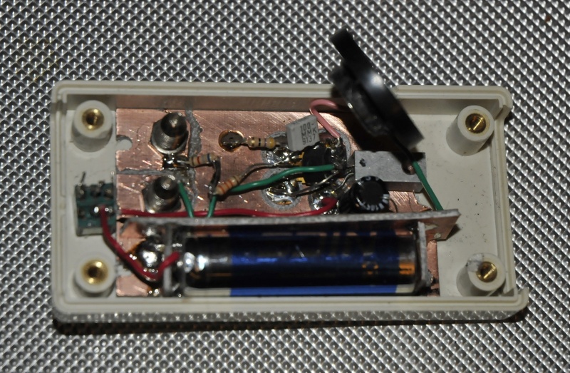
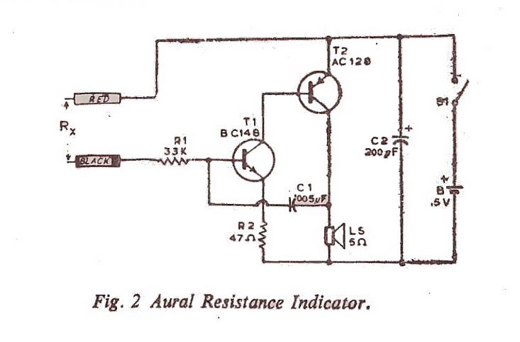
I made some changes but they are rather simple. I have used the original transistors that allready were obsolete in the 70’s, the time the book with this circuit was wrote. But two silicium transistors will work. When testing it, use a 200 k potentiometer instead of R1. Or use it permanent like I did (after the picture was taken and some use) Then short the testpoints and adjust the trimmer until it starts to beep and you like the sound. If it does not beep it probably draws a lot of current so first test with a bench supply. If it does not beep lower the voltage. To much current and the transistor saturates.
The speaker is original 5 Ohm, I used an old unknown speaker in series with a 39 ohm resistor to lower the volume and use less power. Just take a trimpot and try what you like and then replace it for a fixed value (probably somewhere 0 to 50 Ohm)
It is very fast in response. With the power on and open leads it takes 14 nA. That is with a bigger resistor instead of R1 and a resistor in series with the speaker. In the original it drew 54 uA. With 2 silicium transistors will be so low you can skip the switch. It uses a 1.5V AA and is not critical at voltage as long as it is not to high. The second reason I changed R1 for a trimpot is to adjust it when battery voltage drops. In the max position it will stop beeping with a fresh battery and shorted leads but with a almost empty one it will work in that position.
In this setup it sources 2 to 8 uA (short) to the circuit under test at the battery’s EMF so it is save to use. The frequency is in my case 1.0 kHz (short) to 300 Hz (around 1M). If you use R1 as in the original, it draws around 50 mA current around 3.5 kHz and sources more current but still in the uA range. The volume this little gismo is producing with the original parts is amazing.
minimum parts count
C1 is 5nF but I tried 1 to 10 nF and they all worked. The frequency is the result of C1 and R1. The output to the testpoints is DC with a little ripple from the oscillation. The Battery is 1.5V ( the 1 is probably dropped of the paper). Resistors are1/4W and not critical.