At least I hope it will be a restauration because this grandmother of all my generators is in a very sad state.
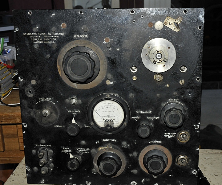
Now I can here you think, ” is he mad ? this is only usefull for parts” but this is a rather special object. Besides that it is a General radio it is very old. I think it is made in the 1930’s . So it is over 80 years old. It was made for radio repair. So it has a whopping 9kHz to 30 MHz calibrated and flat respons amplitude and a not specified 30-50 MHz range. The amplitude is bizar, it can make a 500 nV signal, that is 0,000.000.5V upto 100mV. It is from before the GR-874 time but it allready has three banana connectors on the front. GR introduced these in the USA. The meter in the front is not just a meter, it is a real vacume tube voltmeter (but not accessible from the outside. It shows amplitude or modulation level.
They had a battery option to use it portable. There is no weight in the manual but it is very heavy. I think between 30-40 kilo. The cabinet is made from massive wood (oak ?) and the inside is screened by very thick copperfoil. The scales look awfull but after ultrasonic cleaning and polishing they look as new.
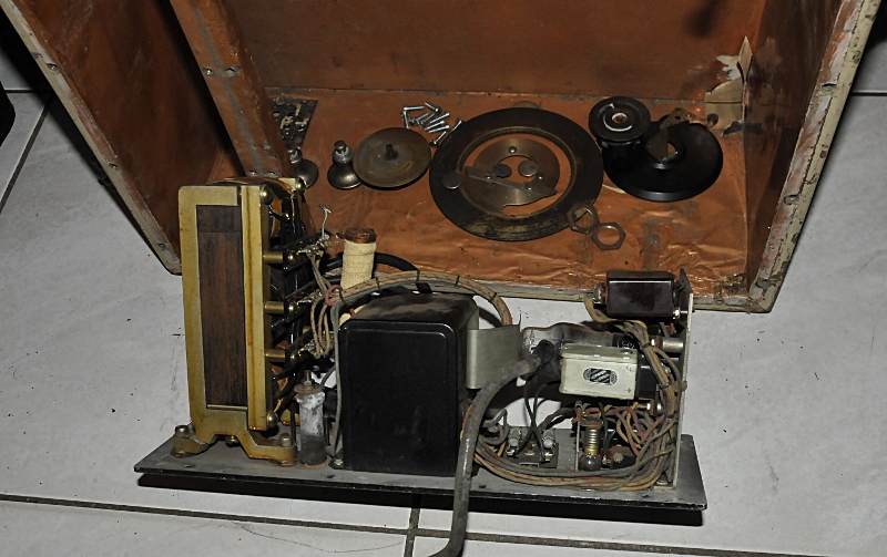
This is de PSU. The huge transformer has one broken foot and there are components hanging disconnected. It looks like some are also missing. The PSU is a ” separate” unit that is build in the same cabinet. The battery option was probably mounted in place of the PSU. Not shure how that was done.
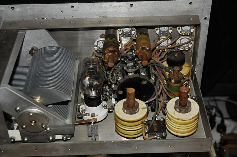
This is a piece of art. The coils are on ceramic cores and placed on wooden pins. The variable capacitor is enormous. Tube sockets are also ceramics. The mica capacitors are also very large and some are bolted to the chassis. In the middle you see the big turret from the band switch.
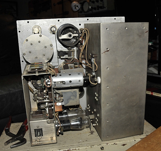
Here the turret compartiment is still closed. Most screws are missing. It is 1,5 mm steel. Not strange this generator is so heavy.
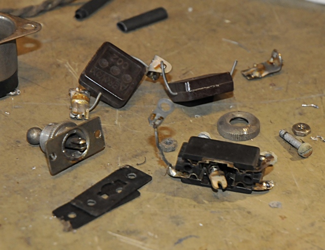
One of the power switches was bad. A high resistance and not a ferm “click” After reassembling it worked like a charm again. The second switch was beyond repair and I replaced it with a GR switch from my junk box.
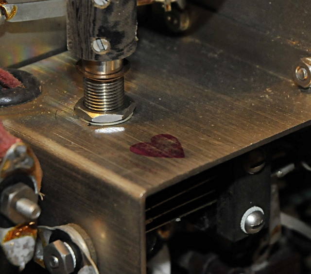
On the inside of the shielded box was this heart printed. I have no clue what or why. Someone must really has been in love with this generator some 75 years ago.
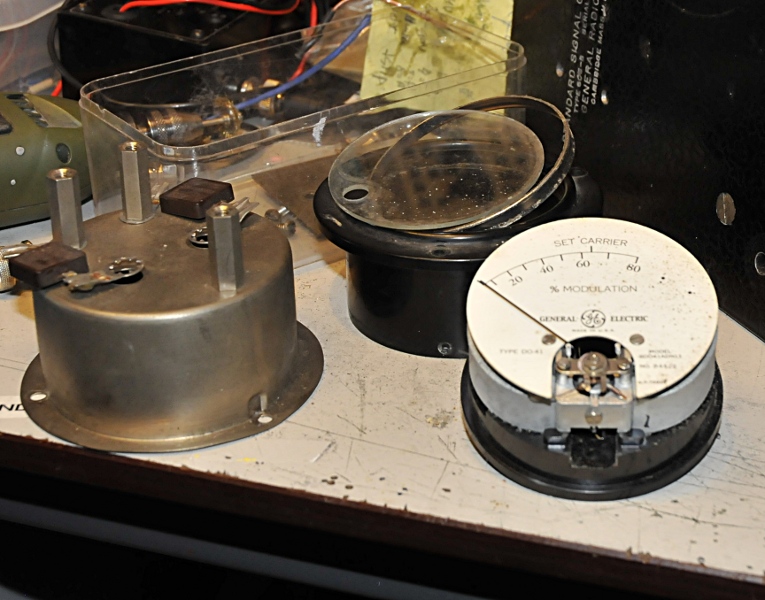
The meter was very dirty inside, the needle was stuck and de glass had come loose.
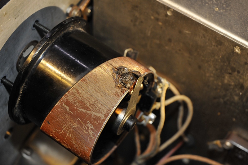
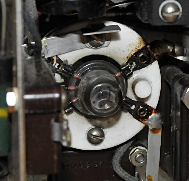
The carrier potentiometer. It is kind a logarithmic and not easy to replace but 2 wires were broken. The repair looks a lot worse as it is. I carefuklly stript the wires next to the broken ones and after a lot of patience I managed to solder a bit of coperfoil over it . After this I covered the whole with epoxy. Here a piece of copper foil is under the wiper but that was just to make sure no epoxy would come high enough. The wiper touches the resistance wire over the whole surface and there is no noticable resistance jump.
In the cabinet are the remains of a tube box that was installed there with a spare 955 acorn tube like you see down here.
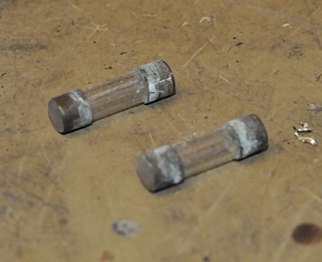 Special high resistance fuses ? (or just dirty 🙂 )
The original fuses. After polishing they are replaced. The caps are made of copper.
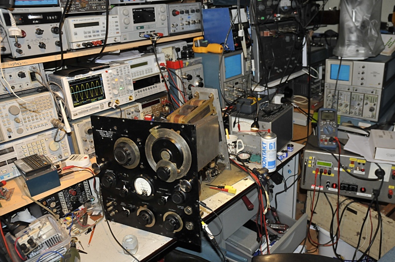
The first testing after the first part of the restauration. It still need some adjusting and some minor fixing. For instance band A and B do not oscillate and the modulation does not function yet. I tested the tubes on my tubetester and they are still very good.

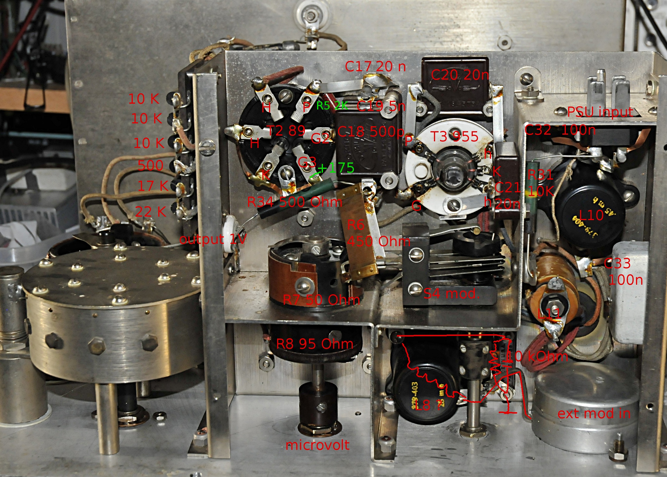
I made some pictures that I fotoshopped as a help while trouble shooting. The manual has no parts layout so finding the parts is a big puzzle. They are rather big files but down here an example.
To be continued.
Update: The powersupply turned out to be the problem. The very rare constant amplitude transformer was dead. One of the windings was broken. Besides that, I think the “black box” thing, probably some filter, was not good too. I thought about replacing the PSU. It would not be very difficult to make something and there was plenty of space. But it is huge, heavy, only 30 MHz and allthough it looked much better now, it was far from pretty. So I stored it as a source for spareparts (things like knobs, meters and potentiometers are used in many GR instruments) to keep my other GR gear in working condition.