
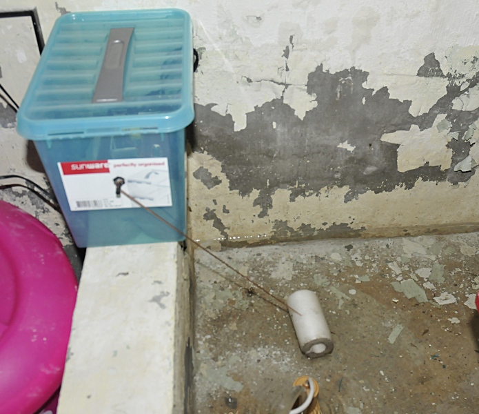
In the basement with the float mounted
Our house has a cellar and there is some strange water resevoir in there. No clue what its use is but if groundwater goes up (I live nearby a big river) this resevoir fills with water and when full, it fills the cellar so I use a small pump to empty it. I used a schematic from an old elector that used some 74 logic and that worked well. But the 3 “antennas” made from VD wire, to detect the level had to be changed 2 times a year because they oxidated. But now there has been a lot of rain and the pump had a lot of work. The problem was that it if it missed a signal it kept off or on. I then must control the pump by hand until I could re-insert the antennas. Now I needed new antennas so a good moment to change the system.
This is a very easy to make schematic that you can use to switch a pump (or a lamp or whatever). The LM311 is a comparator. This is not critical, most comparators will do. I use a IRLZ24 Logic level MOSFET. My pump draws only 3A at 12V. I used this because I want to be sure it switches fast and total (so it does not need to dissipate a lot of power) The place where it is placed is rather damp so I have placed it in a plastic box. That means dissipation must stay low because I can not use a fan and I was to lazy to make a cabinet with heathsink on the outside. The gate of the FET is limmited to 10Vgs ,so I added a 7.5V zener diode. (I made some changes, see the update)
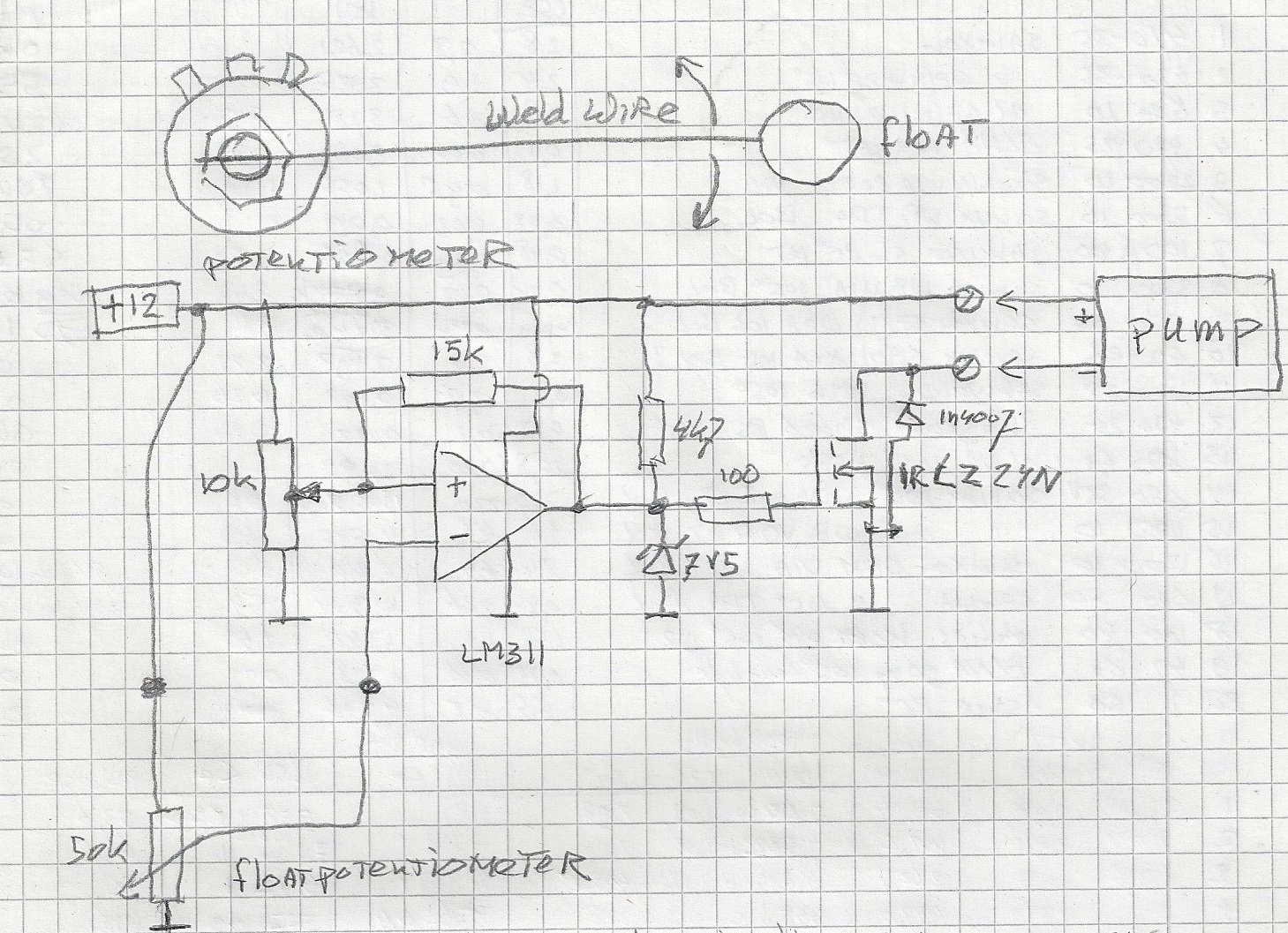
The sensor is a potentiometer with a welding rod mounted through a hole in the axis of the potentiometer. At the end I made a float. As the water level rises the pump will be switched on. The 15 k resistor makes a “window” so it does not switch of again after a few seconds. Without this feedback you get a sort of oscillating pump. I changed that later to 100 kOhm because the window was to large with 15 kOhm.
update: It sometimes happened that the pump kept on pumping at half speed just before it should stop. In that case the FET runs hot. The problem was the powersupply, an old coleman switch mode powersupply from a peltier coolbox. The output was very dirty and caused a sort of oscillations. On my labsupply there was no problem. The spikes of the psu coupled to the gate. If I touched the heatsinck it stopped oscillating. I added a diode followed by a 470 uF capacitor to split the power for the electronics from the power for the pump. This cleaned up the powerrails very nice. Then I added a 1 uF capacitor over the zenerdiode, this made a triangle wave from the oscillating gate signal, so I increased it to 10 uF and that solved the problem. The feedback trimmer is now set around 600 kOhm.
The pump starts around 10cm of water height and stops around 3cm so the pump won’t run hot because it must pump to long and it can not run dry.
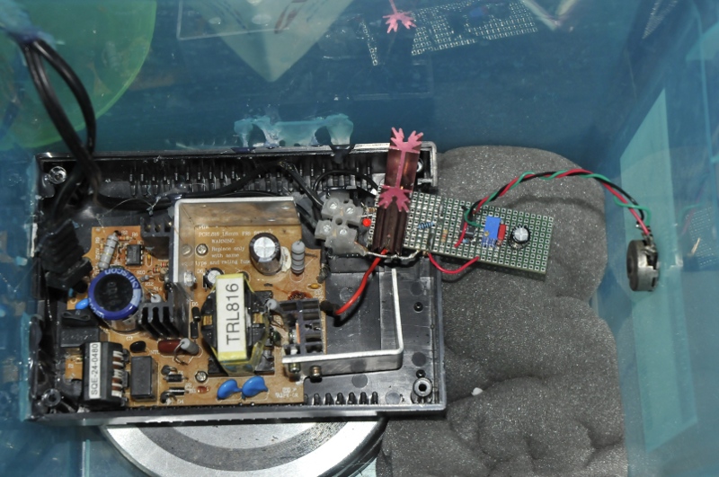
Inside the box on top of 5 kg iron for weight