The History:
On Circuits online Flash2B made a go-nogo opamp tester.
http://www.circuitsonline.net/forum/view/113863
Very handy so I decided to build one too. But it should be more as go-nogo. I want to test things like open loop gain, noise, distortion, offset voltage, input bias etc. Blackdog and Flas2B also liked that idea and so the project went on its way.
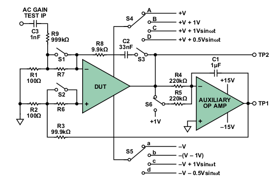
The tester is based on an Analog Devices application note written by James Bryant. A very helpfull man who worked before his retirement many years for AD and still gives seminars (that is where I met him in 2011)
http://www.analog.com/library/analogdialogue/archives/45-04/op_amp_measurements.html
Only problem was that the powersupply was not in the appnote and some tests involve the powersupply like you see at the switch.
Start july 2013:
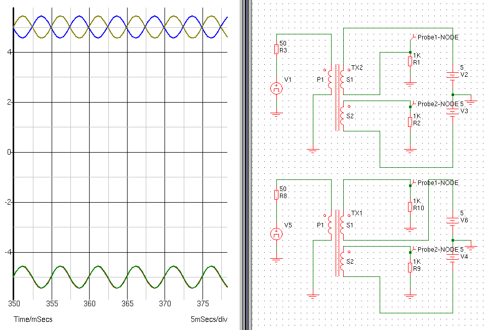
I’m not so into power supply building but Blackdog is, so he is designing that at the moment. There are 3 options. A transformer to modulate the powersupply lines.
For this you can use a transformer and by switching one winding you can modulate the rails in and out phase. This is rather easy but will probably give problems at high frequencies.
The second option is to feed the tester single ended and use a floating ground. In that case you can modulate theground abnd only need one voltage regulator. But in that case you can only modulate in phase. This way of building double supplies was very common in the 60-70’s.
The third way is what Blackdog is designing. modulation through opamps. Separate for each rail. I will post it here if it is definitive. The schematics are for now on that circuits online link.
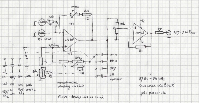
To modulate and test you need a good sinewave. We will make an external input for that but many function generators do not have a very clean signal so I designed a simple but clean sinewave oscillator. You find that soon on an other page of my site because it can be used as base for more things.
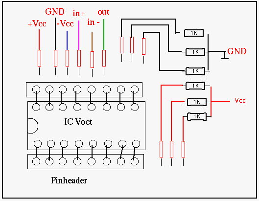
An idea for the test jig:
The wires with resistors are to tie unused inputs or comparator outputs to a rail or ground.
Update Febr 2014; Ready
The cabinet frontpanel is the internal low distortion sinewave oscillator. (See this page; http://www.pa4tim.nl/?p=4502
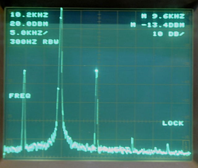
This is the fyundamental at 9.6 kHz. The second harmonic is 40 dB down.
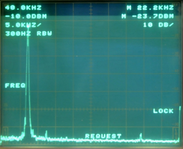
At 40 khz it performs better. More as 60 dB suppression.
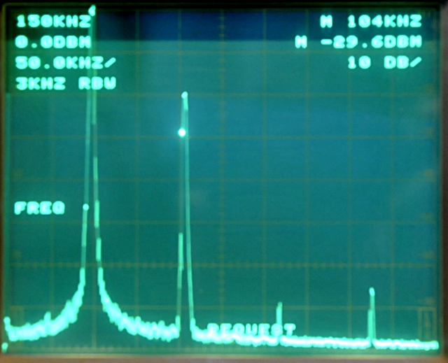
And one at 150 kHz, here it is minus 45-50 dBc.
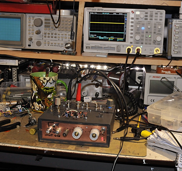
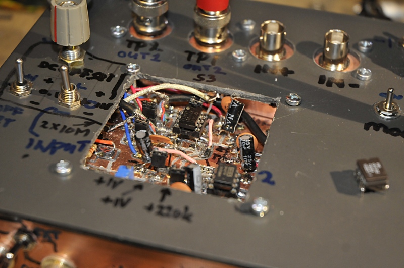
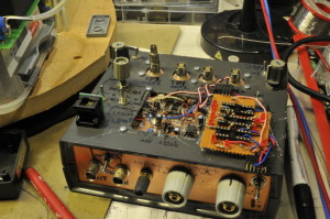
I made a cut away in the top of the cabinet. Here are some jumpers that I use as switch. The opamp under test is inserted in the rear socket. The 4 bnc’s in the back are the two testpoints and I added a bnc for each input of the DUT. That way I can connect things like a VNA to make bodeplots.
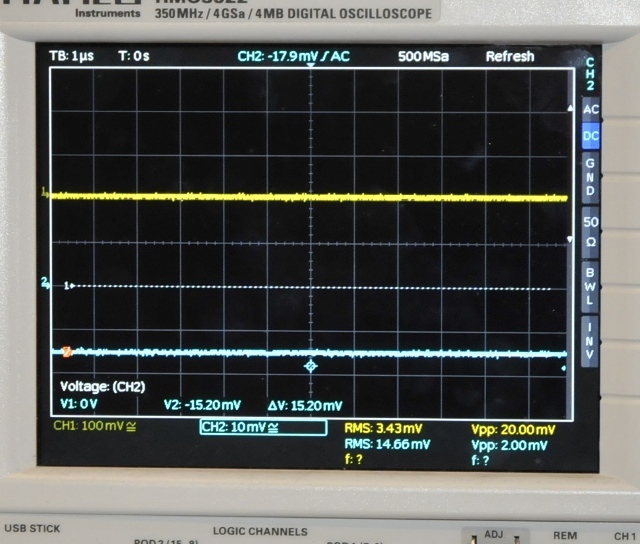
This is one of the tests. The offset voltage max amplified. The yellow trace is TP1, the blue is TP2, -15.2mV offset
Schematic is not very exciting. Just a fixed +15/-15 V supply and a adjustable +/- 5 to 15V supply , two switches that make a -1V step per rail. The sinewave oscillator can be used to modulate the rails or it can be fed to the input for AC gain testing. Besides that there is a bnc to use an external generator for the same function. The most left bnc on the front is the output from the internal generator. To monitor the source while testing. This way you can look for distortion or phase jumps.
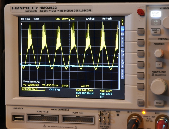
While testing all functions it turned out there was a little mistake in the modulation part. This gave a very funny result. A very hot trace:
Update juni 2015:
I often only want to know if an opamp or comparator is still good. So I added a go-no-go test function. The IC sockets are configured for single, dual and quad opamps and comparators.
I use the psu part to power them so I can test any voltage. I use the sinewave generator for the input. All the outputs have leds. When I turn up the signal amplitude or switch it on/of the led will turn on. I can also test smd opamps through the use of adapters I made and came with my universal programmer.

