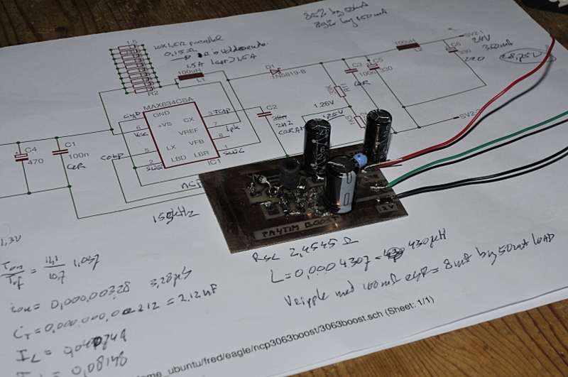
This circuit is a often used circuit for nixie tubes. I wondered how it held up to this one: http://www.pa4tim.nl/?p=4364
This schematic is easy to build, no problem getting it to work but the Voltage regulation sucks. It changes under different ,loads.
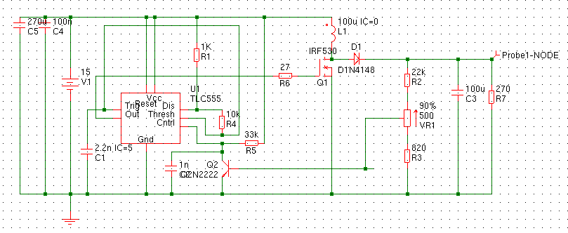
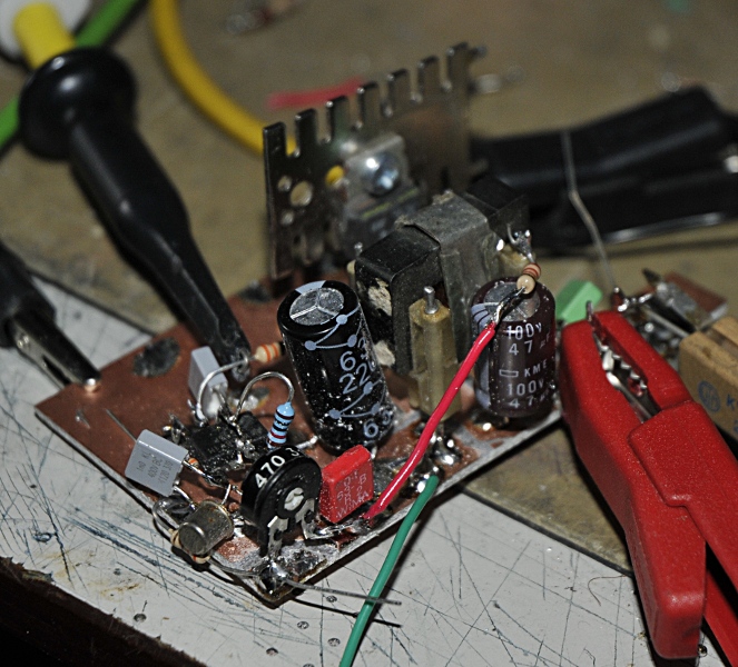
I used a 1nF capacitor for C1 and a BFY90 as transistor. R3 was 330 Ohm and D1 a schottky .
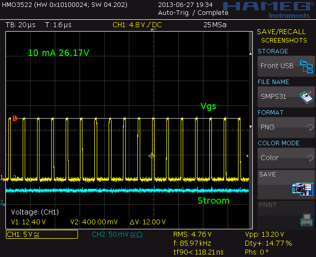
One problem is the voltage does not stay stable. I had to place a 1 nF over the collector, emitor to get it started by itself without a load. High frequency and low duty cycle.
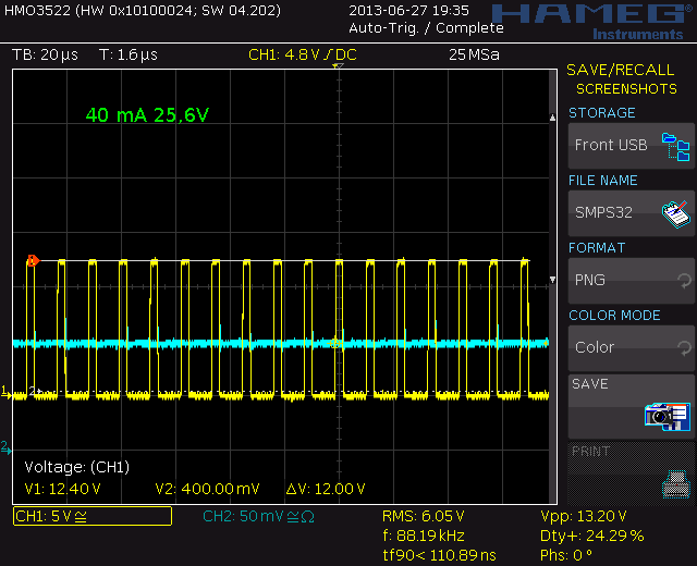
If load increases the frequency and dutycycle goes up.
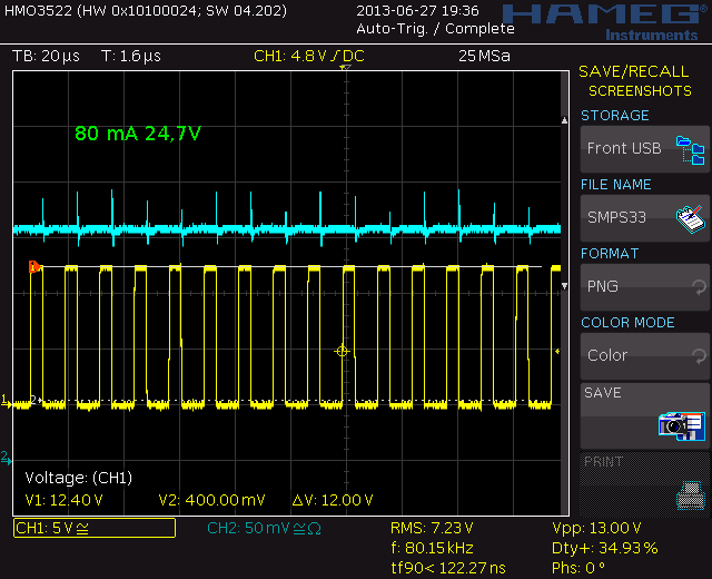
Frequency devreases and dutycycle increases. Here you see the effect of just 100 uF at the output and no filter.
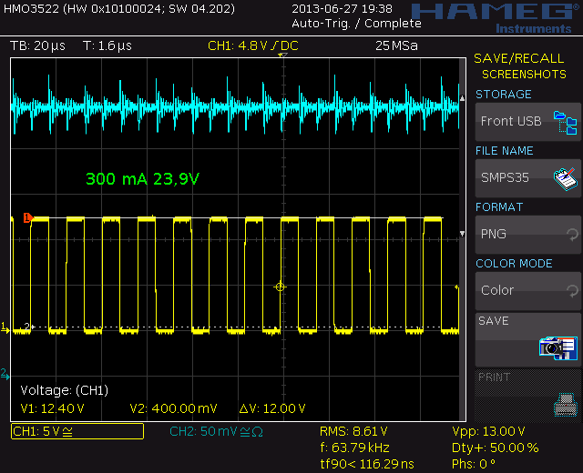
- 300 mA 22,75V, 63,8 kHz, 50%
At 300 mA the frequency decreases further and the dutycycle is 50%. Here you realy miss the filter. Current is measured with a Tek P6042 currentprobe.
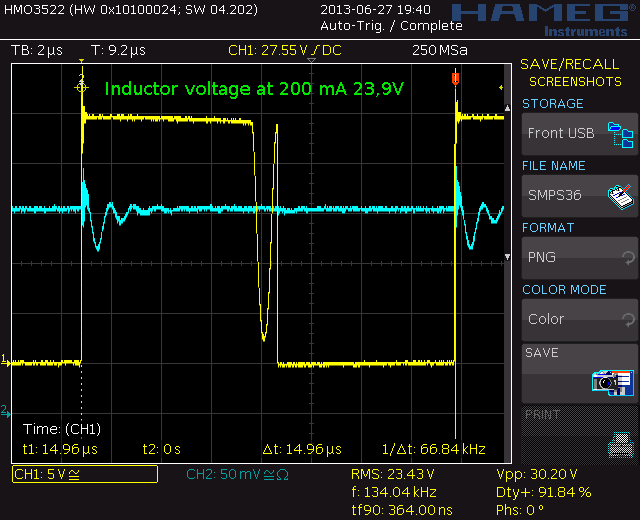
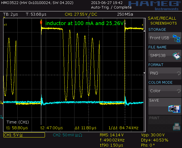
Lets look at the signal on the inductor.
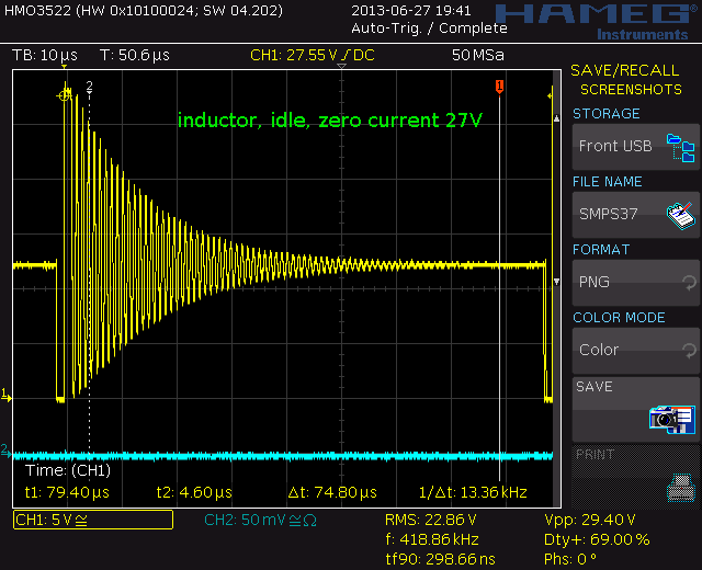
At idle, very nice ringing. (but a waist of energy. The commercial one and my own design the turn more or less off.
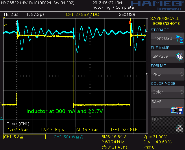
As current increases all energy from the coil is used.
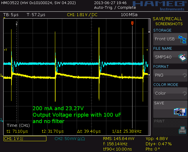
The output voltage with only 100 uF and 47 nF parallel. The spikes are also because I did use a probe with ground wire.
As last test I builded a commercial lopw power boost converter using the NCP3063 running at 155 kHz. It is capable of delivering 350mA is you use a 0,15 Ohm shunt at 24v. I used a 0.2 Ohm and it delivers 28V. At idle Voltage is around 29V but as soon as it start to work from a few mA it is very stable. I only tested up to 200 mA because my coil saturates at 350 mA and I use smd shunts for current sensing. The great thing of commercial inverters like this is the current limmiting. When you go in to current limmiting you see the inductor Voltage going down. This one uses only a coil, timing cap, voltage divider, shunt and schottky diode. No external FET needed. It has an internal Vref so it is not reacting on changing Vin.
The first test went all wrong, desoldered the chip 3 times because there seems to bee a short. After that I decided to take a new one from the same strip. Then I noticed it had a stripe instead of a dot and looked the other one under the magnifier. That was no NCP3063. That was really weird. They came from the same strip. After I soldered the good one in, it worked like a charm. So alway check components.
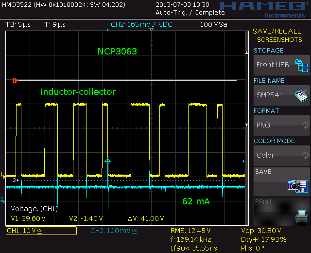
At 62 mA is changes its dutycycle constant. Frequency seems to stay stable around 170 kHz. I calculated 156 kHz so it is close.
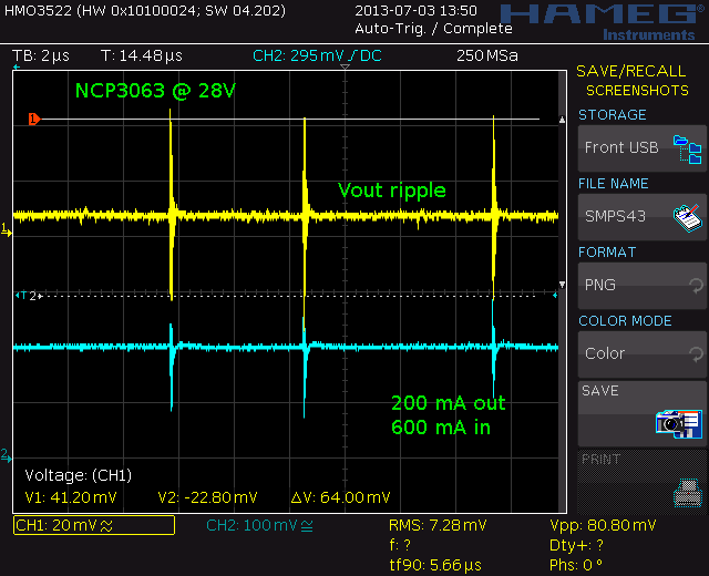
After mounting the booster in a sealed tin box and pass trough capacitors “noise” is reduced from 24 mVrms to 6 mVrms (wideband).
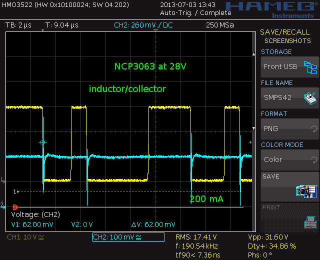
The inductor/collector voltage at 200 mA. No external transistor or FET so the only thing there is to measure is the inductor and output voltage, It has a efficiency around 80%. IO would had expected this better. But output ripple current and voltage is very nice. Also no ringing on the inductor (that is not unusual or bad but it is waisted energy)