While restoring a Fender twinreverb I needed something to use instead of speakers. The amplifier is capable of delivering 135W into 4 Ohm. But it is no problem to use a load with more resistance . I was in doubt between making a dummy-speaker or a resistive one so I measured the impedance of the speakers and to my suprise that had a much greater real part as I would have expected. The major part is R with a rather small +jX part. Impedance was around 7 Ohm at 1 kHz and over 20 Ohm at 20 kHz.
So a pure resitive one will be great for aligning and testing at 1 kHz but will load the amplifier much more if frequency increases. The amplifier normally sees a 20 Ohm load at 20 kHz but now a lot less. That was easy to see when I used a square wave. The left part, the leading edge, of the square went linear up, just like the speaker impedance. So you would think a dummy speaker would be better. The problem is, you must in that case know the impedance of the speaker.
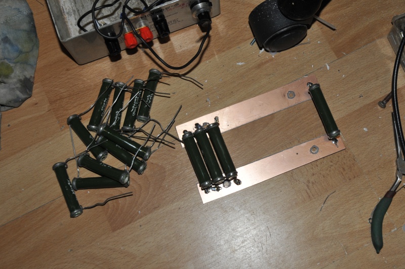
Because speakers have an inductive part too I used wirewound resistors. I had 14 NOS 10W 120 Ohm resistors. I mounted them on two pieces pcb and because the resistors had a metal ring I could use that too, to join them together .
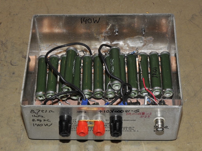
While testing it was dissipating 105W and I needed no forced air cooling. I made a pair of connections for the input and a second pair to connect a TRMS voltmeter. The bnc is a 100x attenuated 50 Ohm output to connect to a spectrum analyser (via an external attenuator and dc blocker for safety. This for checking harmonics while balansing.
The dummy is 8.721 Ohm at 1 kHz and 8.59 Ohm for DC.
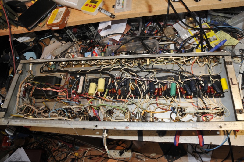
The patient, a 1979 Fender Twinreverb.