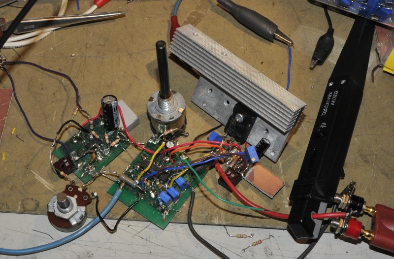
Because my other load is combined with a powersupply I had a need for a small quick to use load, for testing when I make a psu in a project. This is nice to check if for instance your filter caps are big enough. Above is the first test setup. Using one LM324 instead of CA3140 as in the final version. The schematic is based on a design of Jim Williams.
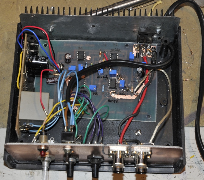
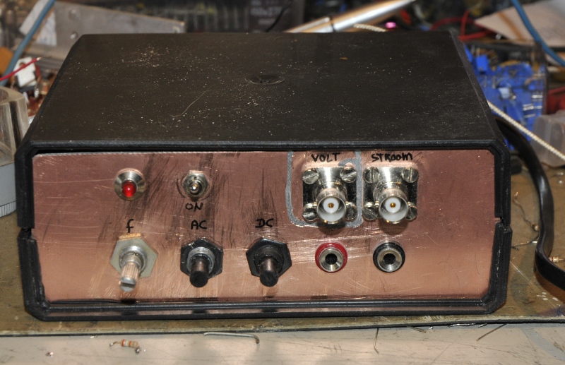
Update augustus 2017, new cabinet, two mosfets in parallel, cpu cooler and a beefy cooled shunt.
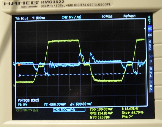
The gate is stepped, I do not know why, probably an offset error. The final version has no problem here.
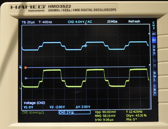
Blue is the voltage at the drain and yellow the current (2A pulses) The PM2811 powersupply behaves very nice.
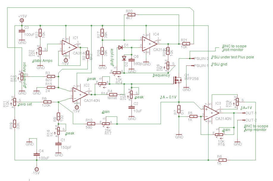
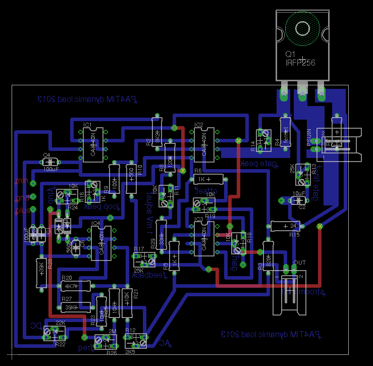
The schematic of the final version. I added an extra opamp. Williams uses a P6042 current probe, I do to but it is nice if I can connect the scope direct or read the current using a voltmeter. The output is 1mV per 1 mA. Update : I made some small changes, like adding some diodes and zeners for protection, add a 10K resistor between the input of the current measure amp and the drain, add a 10 nF over the feedback of that opamp and a 100 Ohm series resistor between output en current measure bnc. Also changed values in the voltage dividers for DC and AC modulation to limmit it to 1.5A but that depends on what you want. I wanted more resolution under 1.5A instead of much power. With a bigger heatsinck the load is capable of much more Ampere. To get better perfomance I changed the ferrit to a 80 uH torroid I tested upto 500 KHz on performance. This gave a very nice and fast response over the whole range.
The MOSFET is a IRFZ256, I tried the IFRL24 but the 256 is more lineair because it needs much more Vgs so it is more easy to drive.
The oscillator runs from 300Hz to 60KHz. But it is easy to make it go over 200KHz. In that case you have a nice job keeping it stable and driving the gate.
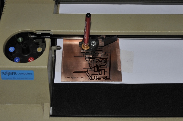
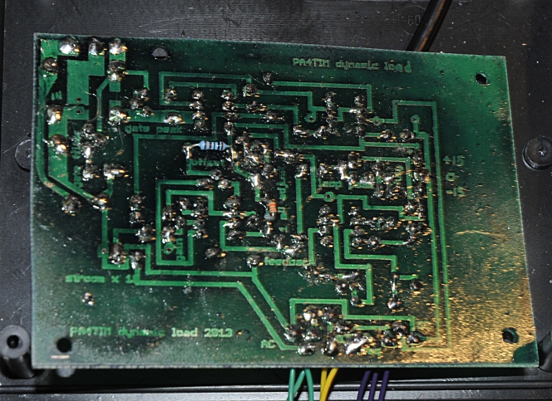
I made a PCB using a HP plotter:
Front without knobs

