ESR is not new. It is not magical, it is not complicated. So it should be easy to measure. Just buy one of the those 50-100 Dollar wonderboxes and you can measure it. But do you now what you are measuring and are they so accurate as they promise ?
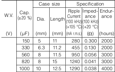
An example, my “fantatest” ESR meter measures a 1000 uF cap at 100KHz. It tells me it is 120 mOhm or maybe 321 mOhm. What do I know ? To be honest, just nothing yet. OK, so I google and manage to find a datasheet for this cap. I’m lucky, the datasheet states a ESR and it is 100 mOhm. So do I have to exchange this cap if i measured 120 mOhm and what about that if it was 321 mOhm ?.
Sound familiar ? So now I am gonna tell how to analyse this, what ESR and related parameters are and several ways to measure it.
There are some problems when measuring ESR:
First, there is a great possibility you measured in circuit, most caps are used on power rails, so there is more then a good chance there are some caps parallel to the one you measure. And some resistances parallel makes a total lower value. So always lift one leg of the cap.
The second problem is that the datasheet gave an ESR, but this is always for a given frequency and temperature. That frequency can be 100KHz, but for bigger value caps this value is most times 120Hz. So always look at the frequency. And be careful, sometimes they state impedance and that is not the same as ESR. But many ESR meters measure impedance instead of ESR so if the frequency is the same you are lucky. And in other cases your ESR must be lower. (you can calculate ESR from it by extracting Xc ans using pythagoras)
ESR is decreasing with frequency. Starting at 120Hz it is almost at it’s max value, DF (do not worry, I will explain that) stays rather constant there, ESR then decreases to a crossover frequency where ERS drops less faster but DF rises. ESR is at it’s lowest value around the self resonant frequency (SRF). So ESR at 120Hz will be a lot higher then at 100KHz. So if you measure 120 mOhm or 300 mOhm at 100KHz and the datasheet tells it is 100mOhm at 120Hz the cap is probably not good any more in both cases.
Third problem, ESR is not a defined quality. Low ESR is relative. What company X calls low ESR can have a higher ESR as what company Y calls a standard cap.
Fourth problem, ESR is most times a measurement in mOhm, the test signal a few hundred mV and the voltdrop over the ESR a few mV, so to get a bit resolution you need enough current. The adc’s used are often 8 bit or if you are lucky 16 bit so they have a tough job. Also is the EMF caused by thermal effects, wire resistance, oxide resistance and RFI most times higher in signal as the voltdrop caused by the ESR.
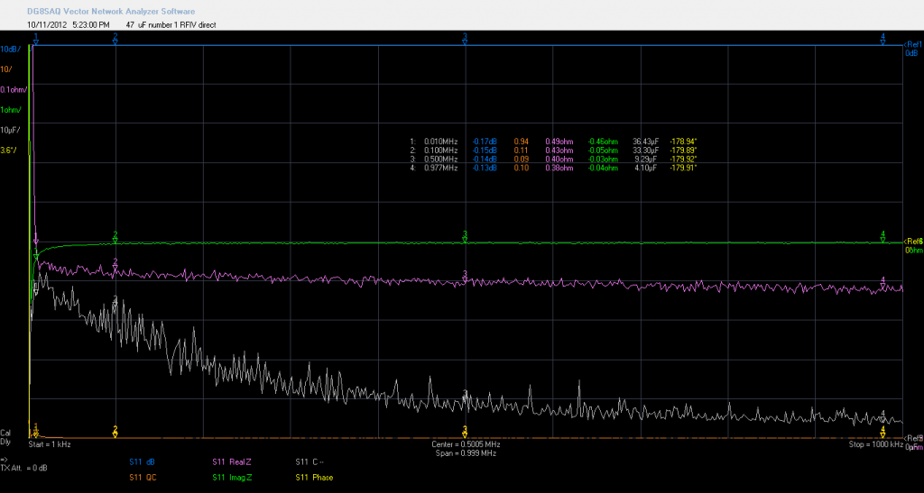
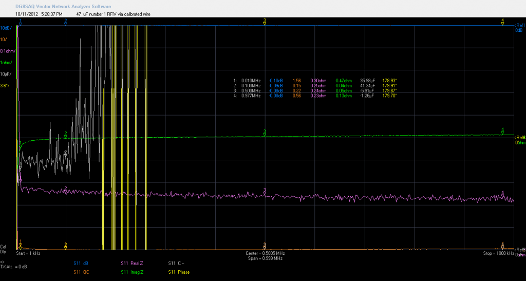
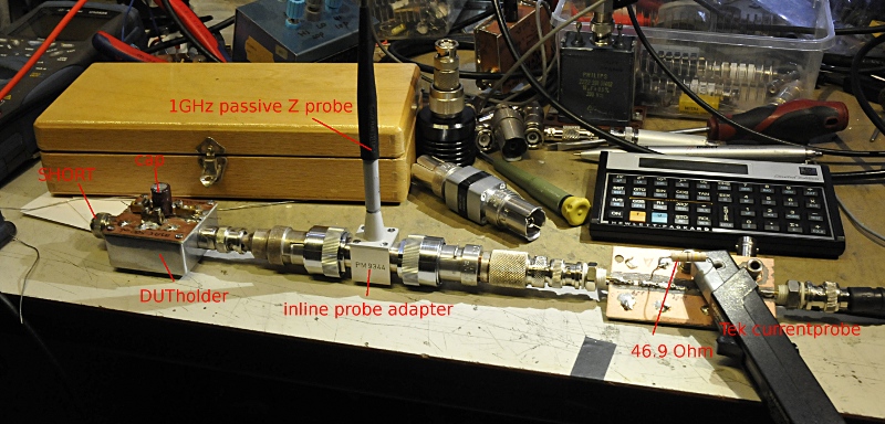
You see the ESR (real Z purple trace) first drop down and then slowly decrease. While DF here rises (DF you do 1/QC) Do not look at absolute capacitance and ESR because I have not de-embeded the DUT holder for that. It is just to show the trends. So ESR is about 100 mOhm aboveMy Peak tell me this new fresh reformed cap is 46.86 uF and 340 mOhm.
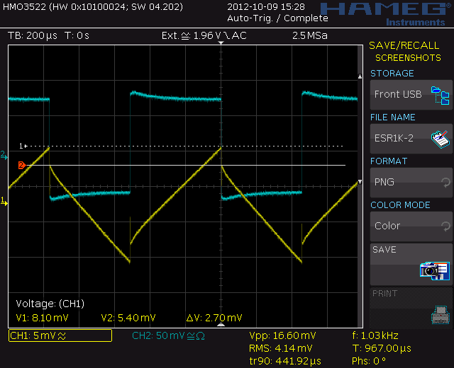
My GR1608 tells it is 43.98 uF and 380 mOhm . The scope squarewave at 1KHz is 385 mOhm. So all very close. The datasheet tells me it is 47uF +/- 20% and max 2,821 Ohm at 120 Hz or Dmax= 0.08. So i still now nothing  So I measured it also using a GR1650 and 1608 using an R&S external generator. The capacitance was 45.4 uF and D was 0.036 So ESR is 1.049 Ohm at 120 Hz. So this cap is well within specs.
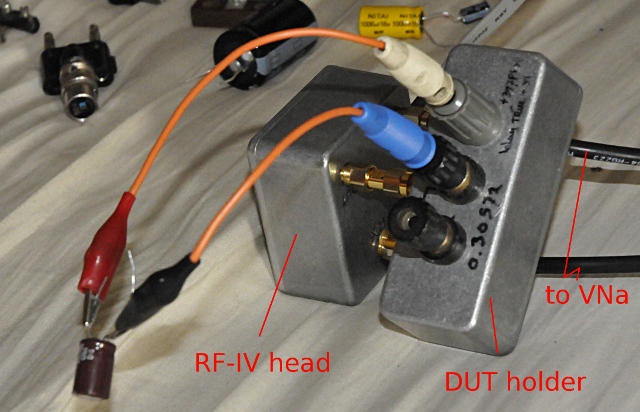
So now I add two short wires, do a short and open calibration like some ESR meters do.
You see at low frequency the capacitance is still is about the same value. ESR is lower and still usefull because I compensated the testleads like the ESR or LCR meter does and the Rs from the leads is at this frequency a constant. But now you also see the capacitor shows selfresonance around 200KHz. And this are very short wires. (one wire here is 138.05 nH and 459 mOhm) So if you use longer and the meters shows capacitance too, this will give false information.
Fifth problem, it can be a “floating” voltdrop that is a very small fraction of the test signal. If your test signal is 5V and ESR is 100mOhm and your test current is 25 mA the voltdrop is only 2.5mV for 10 mOhm this is 250 uV. Most expensive many digit true RMS bench meters have a hard time measuring 250uV accurate at 1 KHz, let alone 100KHz.
So often ESR meters use 100KHz so the reactance of the cap is low. They then measure impedance ESR + ESL + reactance) the reactance ( Xc = 1/(2pifC) ). But they also state a max and minimum capacitance value for the measurement. For instance a 1 uF cap is 1.6 Ohm at 100KHz. If ESR is 0.1 Ohm the impedance will be 1.603 Ohm so the ESR meter tells you ESR is 1.60 Ohm. But if the cap is 1000 uF Xc will be 0.016 Ohm and if ESR is 0.1 Ohm then impedance is close to 0.100 and the ESR meter shows the correct value. I will explain this below some more.
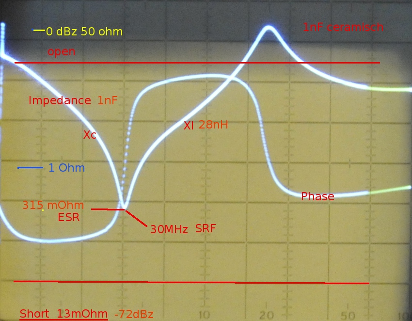
But reactance is a sum of inductance (leads, construction) and capacitance. If the inductance from the cap above is 200 nH (that is called ESL) then, at 100KHz the Xl is +j0.125 Ohm. Xc was -j0.016 (this is complex notation from the imaginairy part of the impedance) so the total reactance will be +j0.109 and the impedance reading of the ESR meter will be 0.147 Ohm. But +j0.109 is not a capacitor anymore, its an inductor. For ESR this does not matter because that is the real part. But there is just a little thing. If the cap is above self resonance like here, the ESR starts to slowly rise (but most times this is not much)
sixth problem, a cap that lost most of its capacitance, leaks DC current can still have a good ESR. So never measure ESR alone. It is, when used wise a handy parameter but you need to know the other parameters too.
But I stop before you get depressed. A ESR meter is often a handy tool if you know what you measure and know its limitations.
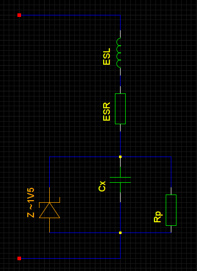
First what is a cap. We start with a simplified replacement model.
You see the cap, Cx, with a resistance (ESR) and an inductance (ESL) in series. The E is for equivalent, telling you it is a replacement for something. If it was only the wires it would be constant over frequency but it is partial chemical and partial electronic. So it is not a constant value.
A electrolytic cap (ELCA from now on, in Dutch we use ELCO from electrolytic condensator) leaks always a bit DC (and so also some AC) This is the Rp. This is in the order of MegaOhms. A 50V Elca that leaks 10uA has a Rp of 5 MOhm
And because the dielectrium of a cap is made out of aluminum oxide there is a diode inside. Every oxide has diode like behaviour, for most elca’s this is around 1 or 2V. If you connect it the wrong way around you can measure this voltdrop, but if you try, use a resistor because the currentflow will be huge and the cap can become so hot it blows up.
This diode can cause distortion for AC signals. Ocide was used in the early radiodays for crystal radio receivers
The leads and construction have some self-inductance so that’s the ESL. Not many people know that there are two sorts of capicitance. The appearant capacitance and the true capacitance. The latter is the real capacitance and you can measure it at low frequencys, the first is a bit complexer. The ESL is a selfinductance, you can calculate its reactance by Xl=2 x pi x f x L it is a positive value (this has todo with complex math, we note it as +jx)
The capacitance has negative reactance. Xc = 1 / ( 2 x pi x f x C) and we call it -jX.
If a 10 uF cap at 100KHz is Xc is -j0.159154 Ohm and if XL is +j0.1 Ohm then the total reactance you will measure is -j0.059154 Ohm and if you do (1/-jXc) /(2 x pi x f) you get the appearant capacitance , 26.9 uF, and this is what your meter will measure at 100KHz . At 1KHz not a problem, but you see, at 100Khz a different story. another example: 100nH is at 100KHz +j0.063 Ohm. A 100 uF cap is -j0.0159 Ohm. So we measure +j0.0469. Yep, an inductor that is 75 nH. So in this case you are already above the SRF. If +jX is equal to -jX they cancel and the result is resonance. The part that is left over is the Real part, the ESR. 100nH inductance is not much but if you use two testwires like on a multimeter it will be much more as 100nH. Besides that the wires have resistance. If you zero the meter, it subtracts the impedance, not only the resistance. If you want to measure mOhms at DC you need a 4 wire Kelvin connection. The resistons of the wires can be as big as 0.5 Ohm, and that on a ESR of 10 mOhm will give a big error if you do not zero this out. The problem from zeroing is that the R and Xl are still there and together with the cap you measure they influence each other so you see, it is not easy.
A impedance is made of R+jx (or R+ -jx) so at resonance we are stuck with R. This is the real part of the impedance. The reactance ( jX) is the imaginair part. So, now you think, what does this all has to do with ESR ? : Simple this R is the ESR.
Now you know some more about what and how I will explain about how to measure this.
MEASURING
There are a few ESR related values that all are related. Datasheets use some or all.
The most known is ESR, already in literature of the 30’s they explained it but they used an other parameter to measure ESR. This is called D or DF. This is the dissipation factor. It is just what it tells. A factor that tells you how much is “waisted” in the ESR of a cap.
It is a ratio. The formula is easy: Xc x DF = ESR or ESR / XC = DF. They uses bridges to measure C and R. The bridge did not gave R but D. But if you know D you can calculate D. But it can only be used at the frequency you measured it. Because ESR decreases relative a lot from 120Hz to about 10KHz and reactance decreases more lineair the ratio does not changes. After the cross over frequency (depends on the cap) the ESR decreases little and Xc starts decreasing so D rises.
An ideal cap has a ESR of zero Ohm so D wil be zero. A real bad cap will have a high ESR and so a D that is very high. Some numbers, D=1 wil tell you the ESR has a 1:1 ratio to the reactance.
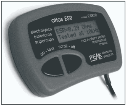
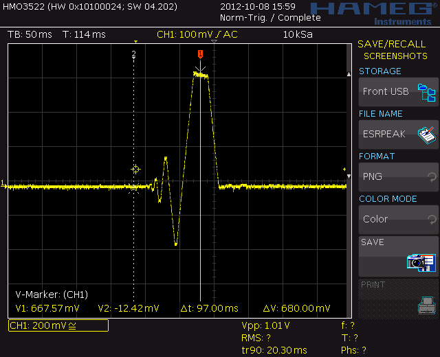
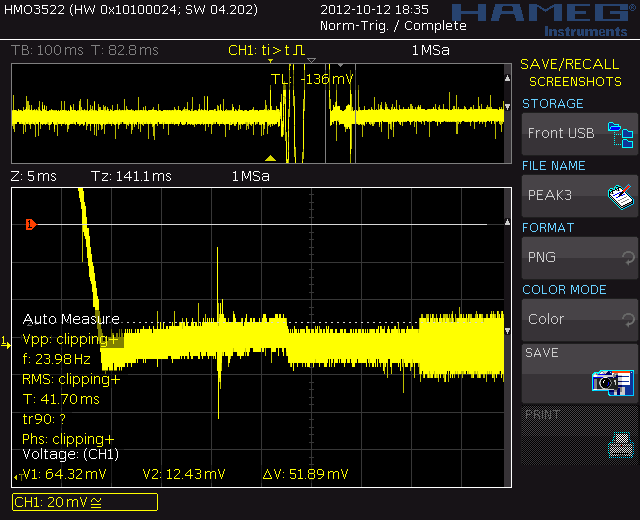
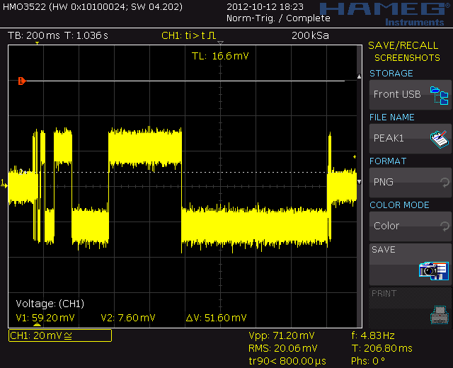
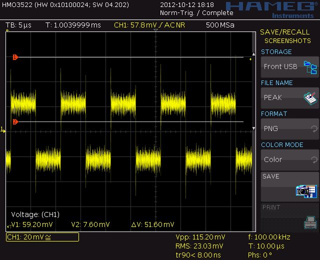
Now its time to measure. I have a Peak Atlas ESR60. This is a handy devise and above 100 mOhm good enough. Under 100mOhm it is not to trust, but who cares. As go-nogo it is good. The funny thing is the manual tells me it measures at 100KHz. But this is what I see. At fist look and filtered just one pulse.
Here you see that pulss is followed by some signal. I decided to use a normal resistor first:
The same pulses are now squares. Now I know where to look I could capture this:
- Finaly the test signal over 11 ohm resistor. Just a squarewave
Just a squarewave but to small to see over a good capacitor. There must be some serious filtering going on in that peak but it looks to me it measures just impedance instead of the voltdrop.
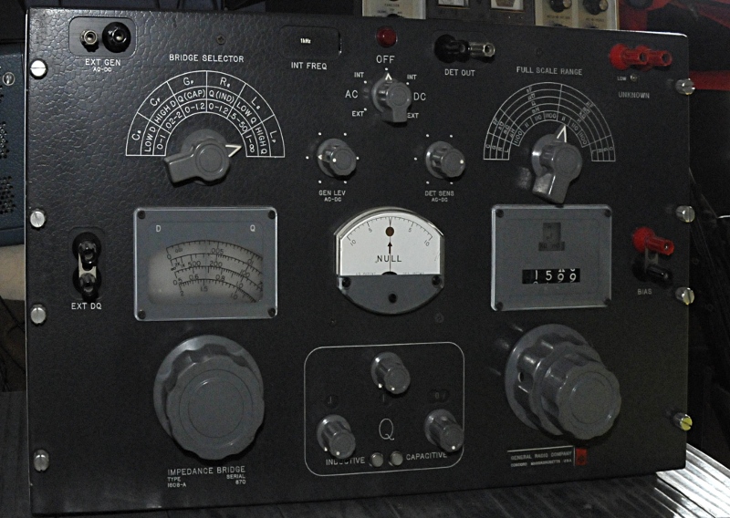
But there are other ways, like using one of these bridges:
A General Radio 1608 LCRG bridge. They measure capacitance and with the knob on the left you compensate for ESR. The reading of that knob is in D. You can use external oscillators for other frequencys, connect external resistor or capacitance decades, used DC bias ect for all sorts of measurements, they are made to last for ever and normally always stay within specs. They are however not easy to use if you do not have experience with them.
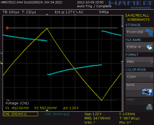
But if you have a squarewave generator and a scope there is an easy way to measure ESR at the frequency you want and rather accurate. This because you see what is happening, so also if there is a problem in the setup.
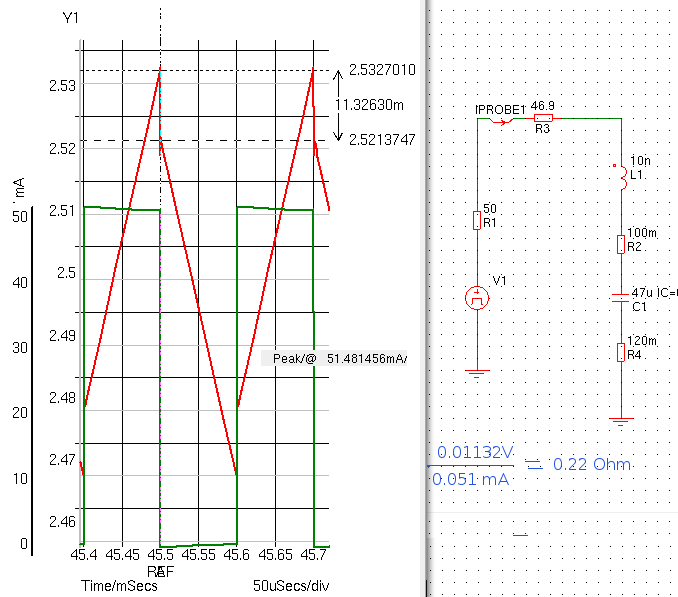
This was my setup. The simulation from the 47 uF cap with 220 mOhm ESR at 1KHz and same voltage and current I used. ESL is kept very small. I measured the selfinductance from one lead of the 47uF test Elca. This was around 2cm and measured 33.2 nH and 5.4 mOhm. So 10 nH is real low. I used two resistors in the model for ESR. This because my DUT holder had a 120 mOhm resistance. I use this sort of simulations to check measurements.
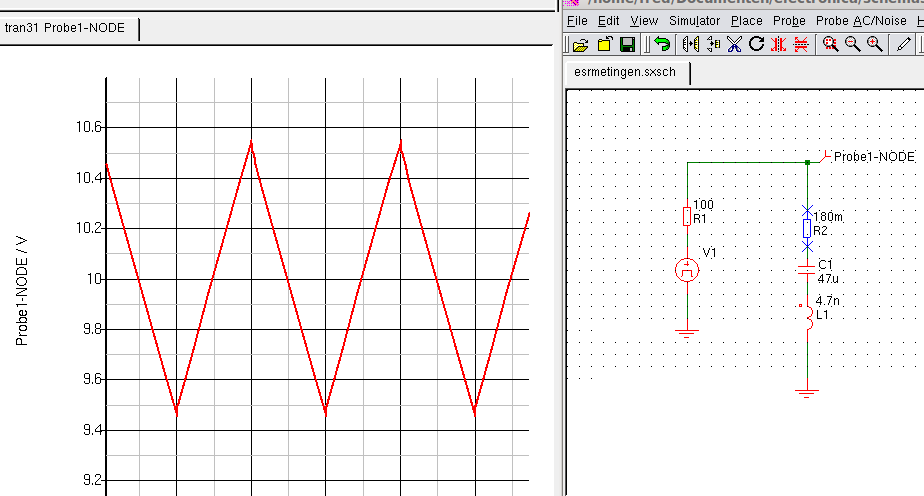
But the scale can vary through higher currents, voltage, capacitance or ESR. The simulation below uses a higher voltage and current.
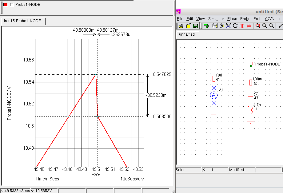
You see, the voltdrop of 180 mOhm is very small. Hard to see but we can f.i. couple the scope AC and look deeper.
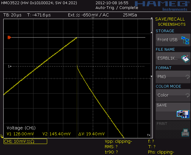
Here you see the Voltdrop. In this case 38.5 mV. But the testsignal is 20V with open terminals. Current here is around 200 mA, and the 0.0385 / 0.2 = 0.19 Ohm. So this is correct for the model used. Esl is here not visible because the low frequency and small value in the model.
As you see, in real live you have the same problem.
This is not from the same cap, that voltdrop was about 1 or 2 mV and i needed the Tektronix Z slide back diff amp plugin to measure that. This is just to show were to look.
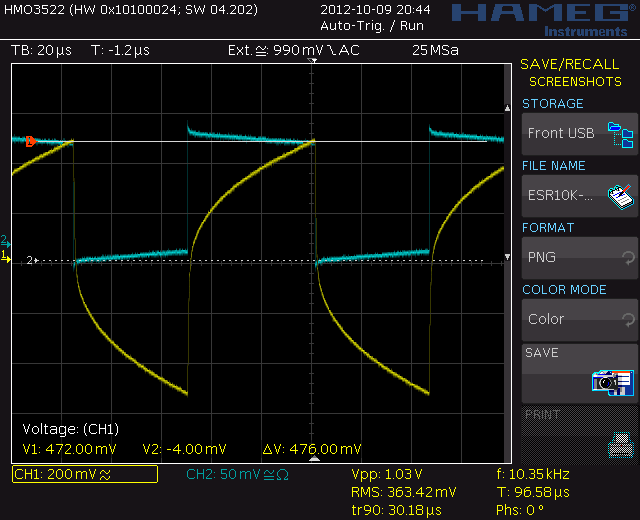
This is a real dead cap, instead of 47 uF the capacitance is reduced to a few uF and ESR is around 10 Ohm. Test current is 46.8 mA and the voltdrop 476 mV. This gives a ESR of 10.256 Ohm.
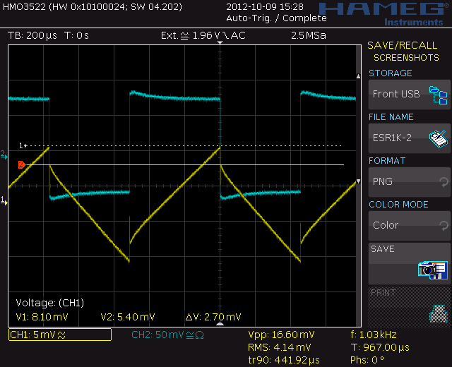
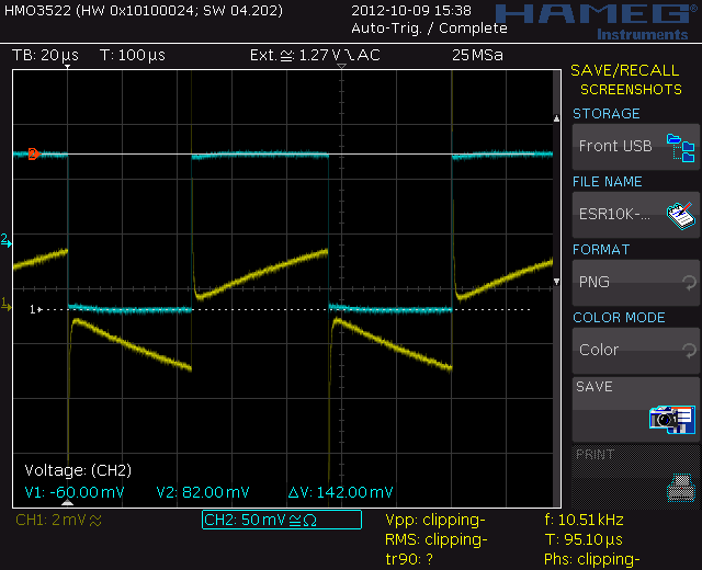
Here the ESR is easy to read, at 1 KHz. You would think this is bad but because it is 1000 uF so Xc is low. ESR is 2.68mV / 53.2 mA = 50 mOhm. ESL is here visible but if you go to a faster timebase it turns out to be 33 mV.
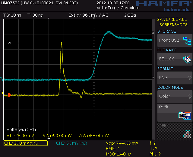
This is a ESL peak at 10KHz. The time/div is 10nS here. Compare that to the 20 us timebase for the normal 10KHz measurement or 200uS at 1KHz. This is 688mV.
An other thing that can happen. At a normal timebase this looks like ESL but it is ringing because I used a normal probe with groundlead here. The cursor still is at the points I thought the ESR drop was using a normal timebase. You see in real it is more as twice this value,
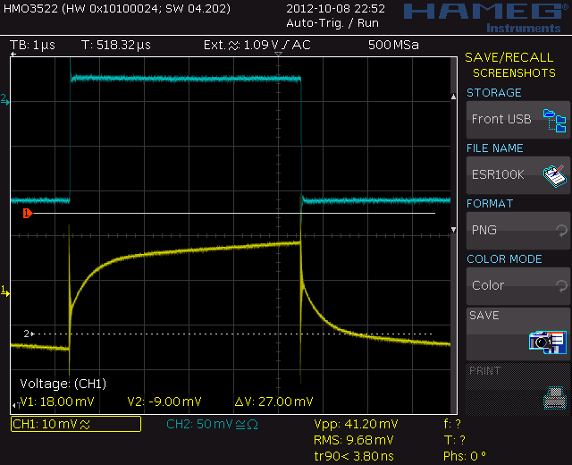
If, like here capacitance is 1000uF you see the shape alter. As the blue trace, the current, rises, the voltage first jumps straight up. This is the ESR. It shoots further up and that is the ESL. The dashed cursor is about where the ESR ends. Then the climb up is caused by the RC time of the cap and resistance of test circuit. You see, instead of a steep long slope this is a short rise. The time is not enough to fully charge the capacitor. This is at 10KHz.
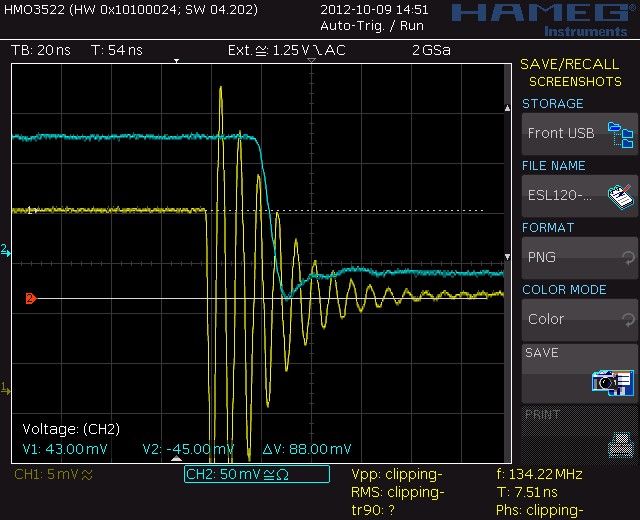
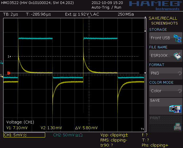
At 100KHz the ESL is dominating. It is hard to tell the ESR here. If you zoom in the ESL is much higher. (do not look at the cursors here.) And if you see the picture below you are above selfresonance.
The ESR voltdrop could be around 5.8mV here but a ADC will probably measure around 20 mV. the down going yellow trace is that of an inductor, the ESL just follows its path instead of cancelled by most of the capacitance.
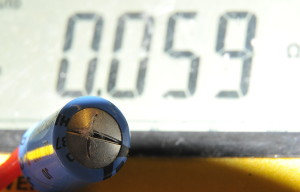
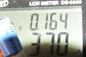
And for the “I only use an ESR-meter” fans. The first picture shows the ESR measured at 100kHz . 0,059 ohm, great, it must in great shape, that is, according to the ESR meter. The second picture shows the capacitance and DF measured at 1 kHz. Also not very bad….makes you think, doesn’t it 😉
http://www.pa4tim.nl/?p=3331 a page with (also some experimental ) measurements on known bad ESR caps . (First part in English)
Some good literature from the makers of worlds best LCR meters, IET labs, the former General Radio:
http://www.ietlabs.com/pdf/application_notes/030122%20IET%20LCR%20PRIMER%201st%20Edition.pdf


