
Allways wanted to know in what health your battery is. There are several parameters that you hear and read about.
Internal resistance (AC and DC)
Capacity to deliver current
Total Capacity left
Voltage (loaded and unloaded
I started with a bunch of bad batteries, reloadable and normal cells. First I measured the internal resistance in two ways.
ESR, the AC resistance using my homebuild one, the Peaktech and a GR1650B
The DC resistance. Unloaded voltage, loaded voltage (15 and 100 ohm) Vload/R=I
(Vunload-Vload)/I=Ri

The difference between Ri AC and DC is very big. The difference between the AC meters is partly because the first to are limited to 20 and 40-50Ohm. The real resistance will be much higher. The GR is not limited.
In a document from Enegizer they talk about the internal resistance of a battery as the opposition to the flow of current within the battery. There are two basic components that impact the internal resistance of a battery; they are electronic resistance andionic resistance. The electronic resistance plus the ionic resistance will be referred to as the total effective resistance. The first is due to mechanial materials like connections, metal ect, the other is chemical. It looks a bit like the ESR of a capacitor, this is also sometimes partial chemical. For instance the dipole effect of a mica capacitor at very low frequency. It looks like the Ri of a battery is more an impedance as a Real Resistance.
Next I started experimenting with the Wilco 60Ah 12V start battery. This was not used for several years and came from a car because it was not loading anymore. It had a Voltage of 7,79V left and a AC resistance of 60 Ohm. I hooked up a loader but no current was flowing. Then I reversed polarity a few times. A 3-5A current started flowing.
After this AC resistance was 650mOhm and after connecting the loader again load Voltage was 12,46V and it drew current 120mA. After a second reverse power trial the The Ri was 3,5 Ohm. After 4 hours loading it raised to 450mOhm and 6 hours after this it was 560 mOhm. After that it dropped to 437 mOhm. Unloaded voltage was 12,76V
After a night rest it measured 2,9 Ohm at 12,56V. I loaded it another day. Then I connected the desulfator and after a night the unloade voltage was 12,64V and Ri= 1,58 Ohm. Then I loaded it with every time for 10 seconds using 15,6 ohm and measured voltage.

The DC Ri was this time near the AC resistance. This because the pulsing gives the battery time to recover. The last 3 AC measurements I split Ri in R-jX.
Then I used my dynamic load to measue DC resistance for the Wilco and for the very dead fiam 12V battery from an alarmsystem.

This gave a Ri of 460 mOhm but measuring on an analog scope is not very precise while measuring mV but my DSO is back to Hameg for an upgrade. AC resistance measured 834 mOhm and 11,6V unloaded voltage. After 10 minutes rest V=12,47 again. AC Ri, kept dropping from in two hours from 520 mOhm to 309 mOhm.
After some time the next photo:

Resistance dropped during the loadtest to 160mOhm. This is strange, it should increase. So this does not seem to be a good way ? But AC resistance was 284 mOhm so AC resistance dropped too.
Then the very dead battery, after some reversing and a bit loading.

Next test was a static loadtest. A “good” ex alarm battery and the 60Ah battery. You read them from right to left. X= time in minutes, Y= Volts

This gives a nice view on the strange things happening. The voltage drops in a few steps and then stays rather constant. Even while the desulfator was drawning 3A pulses at 1KHz. (the grass on the trace) You also see a sort of recovery after a drop.
This was the loadtest and recovery of the “good” battery. The paper is about 2 meters long. The Voltage recovered to 10,87V in 85 minutes.
Today, 30-7-2012 I bought a new Optima 90Ah battery. I measured it before use and extra loading. It was 12,61V unloaded. This gave a value of 0,751 mOhm+j766. This was a surprise, I always read about a battery being a series of resistors with a Capacitor parallel over some of them. 1,5F should be equal to 100Ah. But this showed inductance. about 4,5uH series inductance.
So I measured the 60Ah Wilco the same way again. This gave 3,499-j13MOhm or Cp=172 nF. I repeated the dynamic load test but now loading it at 100Hz with 200mA to 2A. This gave a DC Ri of 611 mOhm.
Then I tested the new Wilco the same way. This gave a perfect square, no lagging or ringing. Difficult to measure because the small delta V. This gave 6,67 mOhm. After some little more heavy loading, upto 6A, I measured 9,37 mOhm. AC measurement was 0,73 mOhm+j7525. The inductive reactance is possible not correct because it involves a lot of math and a very small real part so small mistakes end big, but one thing is sure, it is inductive.
So I took the VNA and measured the old cells again. (i do not dare to couple a 90A to my VNA) Between the cell I had a few known good ones.

As you see there are 5 inductive cells. The nice thing is there are two identical nicads, same age, brand ect. One charged, the other almost empty but both are known good cells. They both have low Ri, DC and AC but they are both inductive. The charged one has a Lp of 30,12uH, the empty one is 2,79 uH. This makes sense, because uncharged and worn they become capacitive. The other inductive cells are also good ones.
Today i replaced the 100Ah for the 90Ah so a change to test the latter better. Start voltage after 3 days loading and desulfator use was 12.6V. The dynamic loading test showed a 200 mOhm resistance but that dropped in a few minutes to 433 mOhm. I also measured AC resistance before the test. This showed a capacitive battery, 250 mOhm and 3,5 nF. After the test it measured 430 mOhm and 4.6 nF so this in accordance with my theory. This battery is not good. But most important AC measurement works a slong as you do not measure impedance |Z| but Z, that is R + jX separated. The first part tells you the internal resistance and close to the DC resistance if you test it dynamic. The second part tells you if the battery is just empty or has lost its capacity. The dynamic load using a scope does the same over time, the AC measurement shows it in a few seconds. Problem is you need a complex impedance measure bridge or a vna. The first not any more in production, but on the other hand, just for this function easy to build one. The vna is expensive even a home build one.

My explanation for these results is the following:
I have drawn the usual capacitor model and the model that is , in my opinion, closer to a real battery. This is not just about lead accid batteries but as far as I tested it holds for lead, calcium, gel. nicd, nimh and plain dry cells. I tested only lithium battery and no lipos yet. The lithium was new but a few years old. It behaved very different on every measurements. They are made to deliver little energy for very long times. I will try to test more types, good and bad versions to see of I get the same or at least consistent results for this type.

If it was like above, the poles had to be connected for DC and they are not. So this model is not possible, exept if you would use a high value R in series with a low R value. The capacitor they model is jhuge, like 1.5F for 100Ah.
My model uses a series capacitor. This is a paracitic capacitor and it is small, for a realy dry and empty battery a few 100pF. The resistors are in serie with it and are the chemical aresistance, metal resistance, connectors ect. The ESL is formed by the inner connections and poles. Between the two therminals is a small capacitance, formed by the test leads and the distance between the terminals. The enclosure in a car is dirty so there will be a high leakage resistor parallel.
If the battery is complete dry, you have a sort of air capacitor. But if the battery is in good condition we are looking at something that looks like a capacitor, that has a capacity (but not capacitance) and is a energy source. It is not like a capacitor a energy reservoir, it is more like a energy factory. So if we apply AC to the plates, the reaction from a cap will be that the opposite plate changed its polarity under influence from the electric field. But in a battery, there is no “neutral”plate system. If we apply a AC signal and it is in the negative phase, the negative battery plates will not become positive. Like A coil it wants to keep the current constant. For a VNA or a LCR bridge the battery behaves more like a coil. It is a sort of current source. It will try to keep the current constant as long as possible. If you do a dynamic load test tou see the current is in phase with the voltage, the current stays very long constant while the voltage drops.
A healthy battery will show a small inductance, the ESL, in the order of nH’s, no capacitance. But a chemical not healthy battery will start to behave like a capacitor.
So DC or AC Ri can be used as a measure of the amount of energy that still can be delivered. If it is 1Ohm the battery can not give more as 12A if you short it. But how long it will keep this up I can not tell. A 10Ah will be able to deliver 10A during one hour. But when is is considered empty. I have drawn in this test batteries to 3 or 4V. For powering some leds this is no problem, but in a car it will have no use anymore. You also can not say, 10A in 60 minutes is 20A in 30 minutes or 600A in a minute. For 600A the construnction must be able to manage this without a meltdown and the total Ri should be below 20 mOhm. This resistance will dissipate 7200W and that is without a dissipating load. If the load is 100 mOhm, you will have a series resistance of 120mOhm. 12V / 120mOhm = 100A. The voltage over the load will be 10V and the drop over the Ri 2V and 200W. This will heat up the battery, heating up the battery will lower the Ri so more current will flow ect. Some types of cell (general speaking, not only talking about lead accid) can get thermal instable and explode.
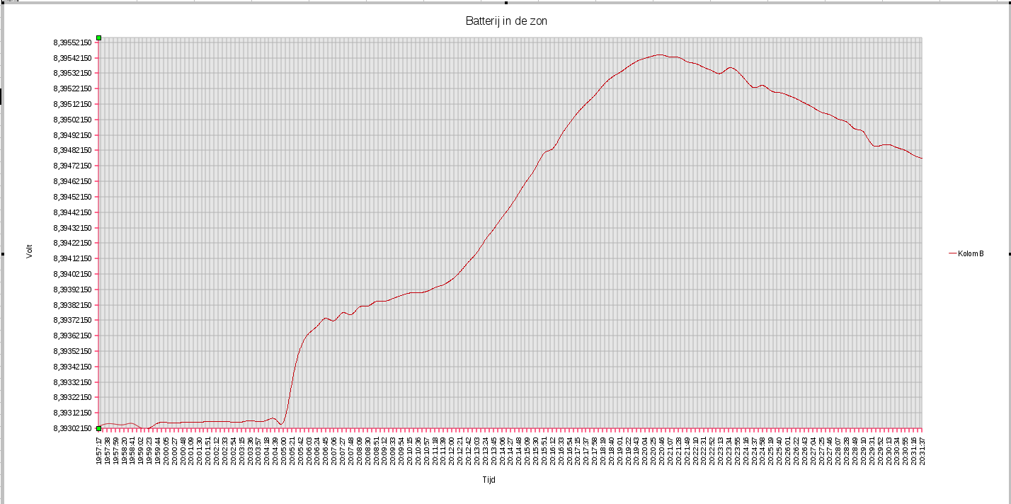
- An allmost empty 9V battery , heating up while the evening sun passed over it
6-2013: Just a little test. I was writing logging software for my Keithley 2000 and testing it with an old 9V battery as source. Not planning to use the data. But then I noticed the evening sun peaking through my window and a beam of sun light crawled towards the battery. During the test it reached the battery and past again. The log periode is 30 minutes and shows he reaction of very little heat on a battery. It looks rather hefty but look at the Voltscale  , we are talking only 2.4 mV.
Update januari 2014: I removed the desulfator and measured the 100Ah wilco battery after 1.5 years desulfating. The voltage was 11.98V and the impedance was 0.180 +j0 so it looks the desulfator has had some effect. I had no time to do a load test.