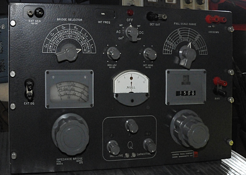
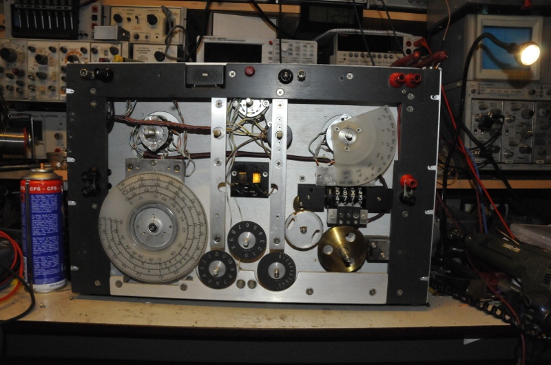
The GR1608 is a 0.1% LRCG LF bridge. The G stand for conductance. So this bridge houses several bridges in one. That is why they named it impedance bridge. A C-series, C-parallel, L-series, L-parallel (L from 50nH upto a bizar 1100H !!) and R-DC bridge. Very common for bridges. But not so common are the extra bridges like conductance in AC or DC (0 to 300V !!) and R in AC (around 1V, 1KHz) . So you can after some calculations measure the complex value of a component. for instance the inductance of a resistor. G is conductance in Siemens, or like they used to name it, mho, the inverse of ohm. 1/R=S so 100 Mohm is 0.00000001 mho or in this case 10nmho or 10nS. It’s G range is an impressive 0,05 nmho to 1.1 mho (20GOhm or like they used to call it, 20kMOhm to 0,09 ohm) Nice feature is the fact the scales are illuminated.
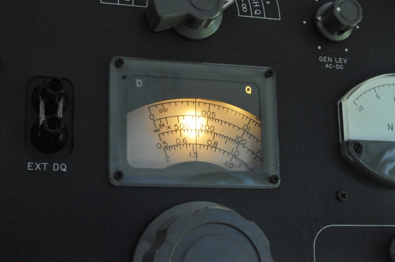
Not so fine is if you have to replace them like I had to do with two of them. The ones behind the DQ scale are a real adventure, you will see more details down the page.
Also special to this resistor based ratiobridge is the very big D and Q range. Most bridges measure a Q upto 30 at 1KHz. This one goes from 0.5 up to 2000 and D from 0.0005 upto 2. When you cap measures 2 it is a really sick puppy. D or Dissipation factor is the ratio between the reactance and resistance. A measure for dissipation of energy while Q, the opposite is a measure for storage of charge. Als a ratio in case of a bridge. There are a lot of flavours in Q. In this case the ratio Rs and Xl. 1/Q = D.
People not used to bridges do get confused because the two options for C and L. Almost all bridges measure the serie or parallel capacitance. If D or Q are normal values, no extremes parallel L or C is about the same as the series value. But if losses are high, the Rs high or Rp part low the C or L value differs. The parallel value is a sort of “virtual” value. It is the same story as G and R, or D and Q. You can transform one in the other, only this needs some more math. Why these double modes if they are about the same ? This makes it possible to extend the range of measurements. Not in capacitance or selfinduction but in non ideal components. A cheap simple LCR meters already goes wrong if there is some real part bigger as a few ohm in the component. Bridges can measure very complex “networks” with high R and jX ratios.
For instance 10uF cap is 16 ohm. If it has a very low DF, lets say, 0.0005 that tells you the ESR at 1KHz is 8 mOhm. Most ESR meters can only dream about that. (but D is like ESR frequency dependent) but if it has a D of 2 the ESR is 32 ohm. Now take a reactance but with a huge resistance. If you model it as a reactance paralleled by a resistor you get the Cp or Lp mode and you use the inverse of the factor. So Q instead of D for a cap. If the reactance is 100 ohm, the parallel resistance can now be 2 Mohm. if the reactance is 1M…. you probably get the picture. So lossy inductors or electrolytics are no problem. You can also measure a cap or inductor using a DC bias.
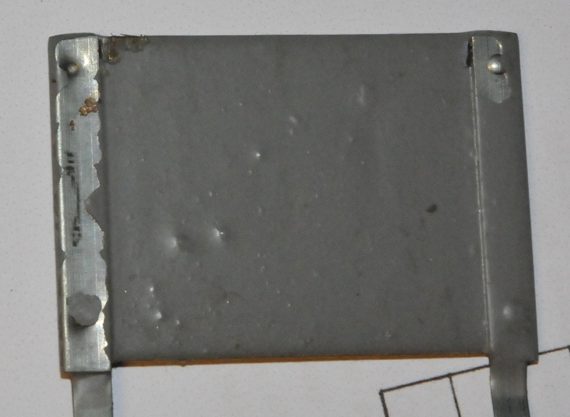
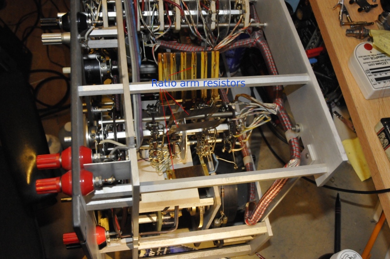
Mine was optical in fine shape but the pF and nmho mode did not work. After study of the schematics I came to the conclusion R13 was the problem, or a connection to it. This is not like the 1615 a ratio transformer bridge but this one has resistor ratioarms. After some measurements it turned out R13 was dead, it is a wirewound 1MOhm 0.025% resistor. It was mechanical damaged. The resistance wire is as thick as a hair so repair was not possible. About 20 wires were broken.
Now I had a problem, were to find a replacement. I found a 0.02% resistor with a 10 ppm TC from Vishay. But it was around 20 euro so it would be a waist if it was not suited because this was thinfilm, so capacitance and selfinductance are not equal. I asked this on the GR yahoo group and to my supprise Henry Hall himself mailed me a manual with larger schematics and offered his help. He told me this Vishay would do fine.
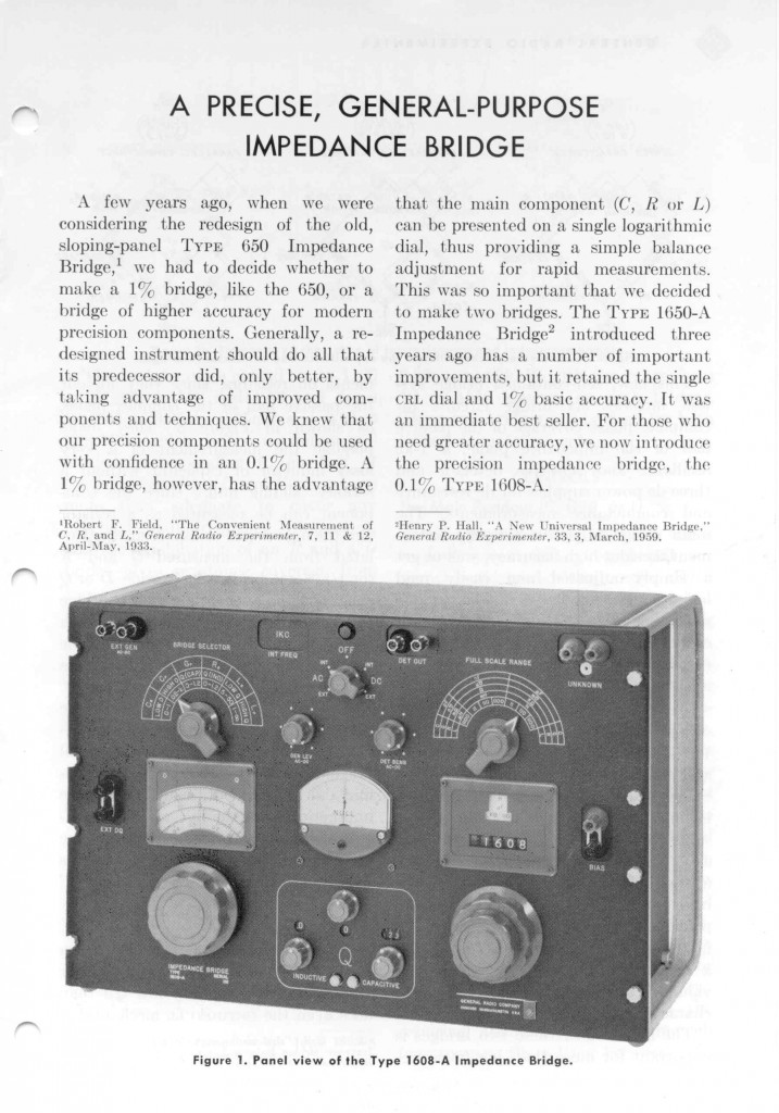
Like most GR bridges this one is also a Design from Henry Hall. He was so famous for his work they even used him in an Add.
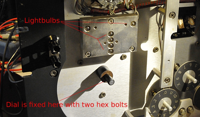
To replace the lamps of the DQ dial I had to remove this dial. There are two hex bolds on the boss on the rear of the dial. Then you need a lot of patience and care to remove it and make a good marking of the position. Behind it the next obstacle:
The lights are in this alu block. So screw it off and the you desolder the wires and you can remove the lamp. They are working at a much lower voltage as rated so they last allmost for ever. The one here was not bad, someone had replaced it and used to much solder so the spring no longer made contact. The other after the units scale was dead.
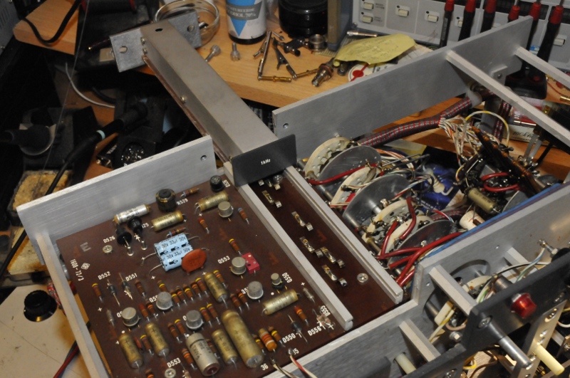
The brigde workes at 1KHz but you can connect an external oscillator and external detector for higher resolution. The oscillator is a plugin. The sold other frequencys as option. You slide it in from the rear.
Next step will be a good check of the detector , powersupply and oscillator circuits and a calibration.
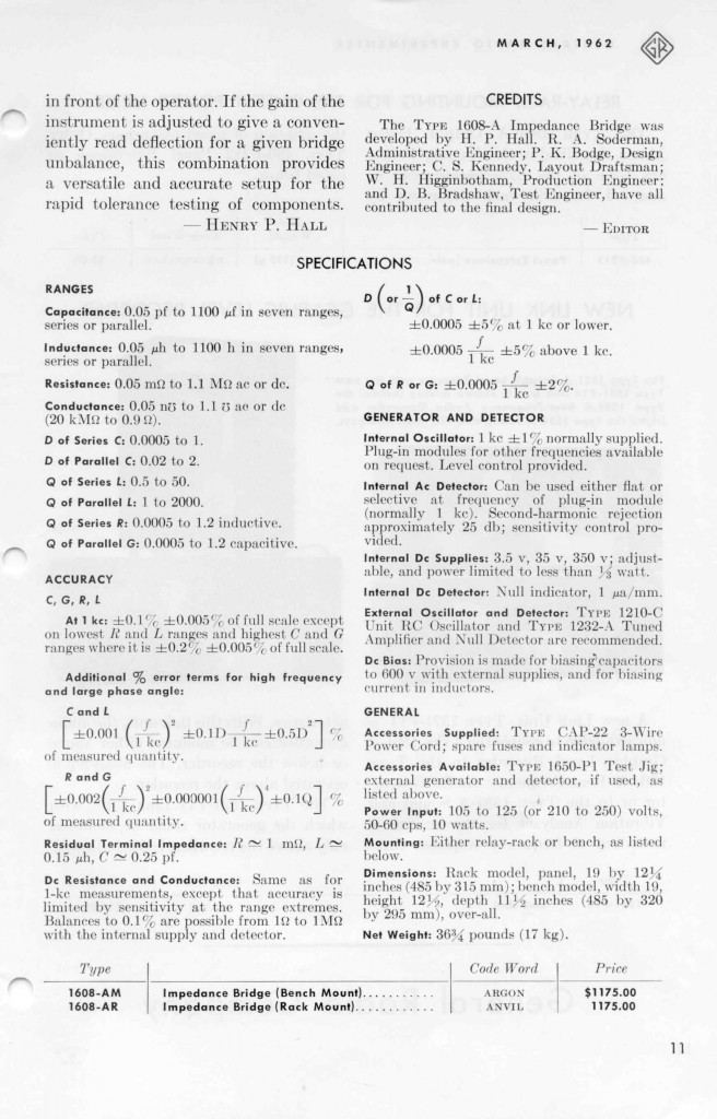
Specs and first page of the GR experimenter at introduction date

