
When I bought my Tek 7704 and 7603 from an other collector who needed more space, he gave me a P6042 probe amplifier without the probe. Only the cable was there, the probe was missing. These probes are very delicate. But the problem is not always the probe. In my amplifier the cable was broken inside at the location where it enters the cabinet. That is not a very well made construction. On the other hand, it is over 40 years old…
I found this problem when I experimented with a home made AC+DC probe. Those experiments also showed it is a hell of a job to make a probe like the original.
When I was searching for a replacement probe, I asked this on the Yahoo Tektronix scopes group . One member told me, the simpelst way to find such a probe, or try to make one, is to invent a time machine, travel to the 60’s and buy one….
But I was in no hurry, I then did not know the advantage of having a current probe like this. On the same Yahoo group there was a Swedish guy who calibrated , among other gear, Tek current probes and he just had one that was outside specs and replaced. Only problem was that is was a much newer one from an AM503 probe amplifier. But for 12,50 euro included shipping it was worth the try.
The main difference between both systems is the electronics, not the core of the probe. A P6042 probe is a non-replacable unit. The amplifier is optimised for the probe that is mounted. The amplifier has several hand selected parts and locations to mount more of those parts, so they were able to always mach the probe. That was a one time job because the probe was permanent connected.
The AM503 amplifier was an other concept. Here they made the system in such a way it was possible to use it with any probe made for a AM503. So if you had several systems you could exchange the probes between amplifiers. The amplifier has a very limitted adjustment range compared to the P6042. Here it is the probe itself that can be “adjusted”
There was nothing wrong with the probe I bought, it was just outside the specs to use it on a AM503. But this was not the case for the P6042 amplifier. However, my amplifier missed more parts. The most important part, the hybred front end, was in a good shape. If you have a bad one, look for the app note Jim Williams wrote about making a modern replacement with a handfull of LTC parts.
In my case the power amplifier transistors were missing and they are selected parts too. I spend a lot of time matching those on my curve tracer. It worked usable but it took a while to stop drifting. UPDATE, see below: In 2014 I decided to take an other look at the amp because I could not get it right on the most sensitive ranges and I used it a lot. I spend a lot of time optimizing the amplifier part and the probe. The warm-up drift is still there but besides that it is working fine, and now in all ranges. I also made some changes to enlarge the offset and DC adjust circuits.)
I mounted a Lemo socket on the amplifier cabinet and added the male Lemo to the AM503 cable.
Why you need a AC+DC current probe ? The main advantage is measurements on switched mode powersupplies, or any psu followed by some digital devise like the raspberry pi in the screenshots below. A normal multimeter can not handel this kind of waveforms. Most TRMS meters are also of little use. Only a TRMS in AC+DC mode capable of measuring signals with a very high crestfactors and has a high bandwidth, can be used. Together with a good DSO you can measure RMS current and voltage from signals most TRMS meters can not handle. And using the math function you can measure power.
An other example where I needed the P6042 was the repair of a few HP-9100 calculators. That thing is one big current source, almost all the digital stuff in there is current driven, like the signals to and from the “memory” .
In the pictures the behaviour of a Raspberry Pi : Yellow is current measured with the P6042
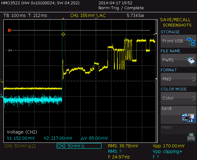
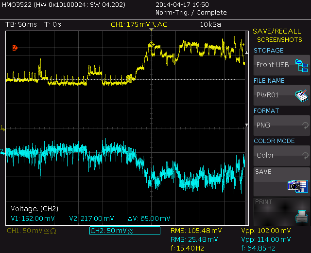
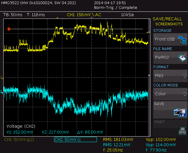
The first picture is the Pi booting, the rest is just random while in use. The powersupply is a classic transformer type good for 5A.
TheP6042 or it’s close related sisters like the AM503 is one of the best current probes ever made. It is capable of measuring AC+DC. Upto 50 kHz the hall sensor does the job, above that a torroid takes over. The transit between those modes is the biggest problem and the reason they made this probe for decades. It is a class on it’s own with very little competition.
The P6042, 6303 and 6302 are close related. If you have a dead one, first check the cable. I used TDR to find the location. It is where the cable enters the cabinet. If you want to adapt an other probe like I did….. it can be done but it can be a hell of a job. There is no receipt, these probes and amps are made over a long period of time and stuffed with hand selected parts. You have to measure and translate the results to your combination. This involves a lot of trial and error. But calculate voltages and currents first before you test things. Using a simulator can be handy too. I often do that to check if my thoughts about a part of a circuit are correct.
Be very careful, do not try random things without calculations first , you do not want to fry the Hall sensor.
For reference the connections of my AM503 probe. Thanks to Sparkey who opened his probeconnector for me so I could sort out the functions (mine was without the connector, so very difficult to find the function of each wire)
-16V is red, de source that biasses the Hall sensor
+16V is orange, also the Hall sensor
offset is brown but not needed for the 6042 amp.
White and yellow are the Hall output.
Two shielded wires go to the current transformer.
The current for the sensor is determed by two selected resistors. They are around 670 Ohm and cause a + 3 and -3V over the sensor. The 6302 probe amp has no resistors and here the probe itself has them. This because the probe must work with more as one amplifier. The sensor is biased through two 240 Ohm resistors and a 3V3 zener. I got best results without the zener and I used two 470 Ohm resistors. (This was the original text, see update down under for later made changes/ improvements)

The probe is very easy to dismantle, but be carefull. There is a tiny metal ball. That is lost before you notice it.

In my case the Y amplifier was dead. The hybrid diff amp after the sensor seemed to be defect also, so I made a new one but that gave the same behaviour. At the end the power amplifier was the real defect and combined with the offset of the probe and many variable factors caused by the small differences between probes, this was not easy to find. The first repair made it usable but not in all ranges, that is why I gave it a second try a few years later. After building my own Hall amplifier I better understood the “mechanisme” involved and now it is fine. I have no clue about the drift on an original combination but mine drifts about the first 10 minutes a little. I think that could be normal.

The transitors had to be matched pairs. That costed a lot of time and is done by using the Tek 576 curve tracer.

Update may 2014 :
After playing around with a Hall sensor and some study about the way they work , I decided to redo the P6042. It worked and I used it a lot, but it had to much drift and that made it hard to operate under 50 mA/div. Like you can read above the probe is a close relative from the original but not the same. I experimented again with the amount of current. Extracting from documentation and measurements I found a setting that gave good results. I took the output from the hall sensor as a guide. I placed new resistors with 100 Ohm 10 turn trimmers in serie. Then I altered the offset resistors until the trimmer on the front had the right range without altering the gain. After that I did the normal calibration. It turned out to have a very low noise level on the plus/min 16V powersupply rails. This is important because that 16V is also used for the Hall sensor. The P6302 uses zeners for Hall bias and those add noise. I do not have the zeners in the probe, nor in the amplifier so that is probably the reason for the low noise.
The result you see in the screenshot:
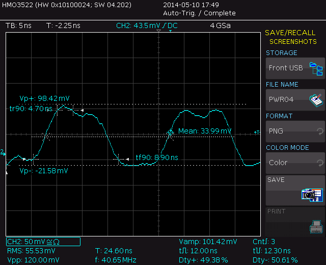
This is a 40 MHz squarewave generator with a 500ps risetime. The probe is set at 1 mA/div. The generator has a 134mVpp amplitude fed into a attenuator and measured through a loop shorting the output of the attenuator to ground. Not bad for such a small fast pulse.
The bandwidth of the probe is 50 MHz but for a 40 MHz squarewave you need a 200 MHz or better bandwidth. The limmiting factor is the probe. The time the P6042 was designed, 50 MHz was a very good bandwidth for a scope. The 547 was also 50 MHz and one of their finest scopes. The screenshot is far from a perfect square but still recognisable as a square. The scope is 350 MHz. This results in a bandwidth for the probe/amp better as 75 MHz.