
The Tektronix 576 was in that time so expensive that it did not sell in big numbers. That is why they made the 577. There is not a huge difference. The 576 is wider , has a readout and I think the 576 is more user friendly and can measure more accurate thanks to things like the zero button and offsets in calibrated steps. (I had a 577 too). The read out uses a rather expensive fibre optic system.
I have several passive adapters. A curvetracer can do a lot more as most people think. It is what you call today a SMU. A source that can measure.
Besides testing semiconductors you can use it as a lab supply, test caps on leakage and ESR, test transformers, test and charge batteries, test IC’s (signature analyse), check relais, test tubes, match neons for a chopper, match leds etc. It can do 1500V and 20 (220W) . You can choose a fixed DC, DC sweeps and AC. The stepper makes upto10 steps in current or voltage. You can use it in situ as a Hutron tracker
There were other plugins available, f.i. for measuring things like voltage regulators.
The display shows the voltage on the X-axis and the current on the Y-axis. That is, in most modes. You can choose a max voltage, emitter resistance coupled to a max power. For 3 pin semiconductors like a transistor you can choose the number of steps, if you want a voltage or a current step and the magnitude of each step. Every step gives a trace.

This 576 was used in the callab from a big company. This lab closed in 1988 but all the gear stayed in that climatized room. I did the usual thing to wake it up and checked everything. It was in a new-like shape. No damage on the outside and very clean in the inside too. It was well within the specs.

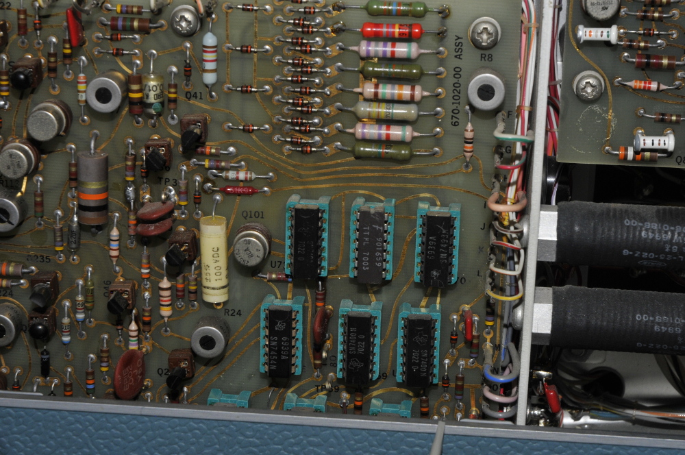
In the back are 2 low voltage pcb’s. Not very handy placed if you need to repair the second one. To make it even harder the filtercaps are mounted behind the PCB’s.. Ter verhoging van de feestvreugde zitten de voedingselco’ s daar weer achter. If you need to replace them you need to remove the boards and the (rare) CRT. The PCB’s next to thr CRT are the horizontal ,vertical and stepgenerator circuits.

The other side holds the high voltage circuits and the high power collector supply.

This CT dates from the early 70’s.

These are the DUT adapters.

From here some explanation, but only in Dutch. Maybe one day I translate it. Most of my site was in Dutch. A lot of work to translate everything.
Update june 2015: Repaired it after the stepper died. The problem were 5 dead 74 logic IC. The IC’s are in sockets and easy to replace. I used a logic probe (HP-435) to follow the signals and that is a very fast way to find bad IC’s. I’m glad they did not use special Tek parts.

Dit is de gm of transconductance. Even getekend ipv foto’s. Dit is een BF245 jfet
Ingesteld op 1 step van 0,5V. De onderste lijn is dus de drainstroom bij 0V Gate spanning. De tweede lijn bij 0,5V verschil. De Xas is drain spanning. De CT geeft hier 4mho/div dus je kan gm direct aflezen. Foutje in de tekening, de source hangt aan gnd natuurlijk.

Hier zie je hoeveel Id stroom er loopt bij verschillende Vd waarden (x-as) met de gate aan gnd.

De stroom die er loopt vanuit de drain naar de gate die aan gnd ligt met de source open. Hierbij wordt de spanning tussen gate en het channel zo hoog dat het doorslaat. Met een CT is dat te meten zonder je FET te mollen. (als je voorzichtig bent)

We hebben gezien dat wanneer de gate aan massa ligt er een bepaalde iD gaat lopen. Dat is bijna de maximale. Er kan soms nog wat meer lopen doordat er gate stroom bij komt als je de gate postief maakt tov de source. Bij buizen speelt dat vooral een rol. (dit gaat over een BF245 jfet, er zijn veel soorten FETS, MOS, jFET en dan is er nog depletion en enhancement mode) Deze FET gaat bij -4Vgs in pinch off, er loopt dan geen stroom meer.
Je kan er ook buizen mee testen. Het is mogelijk, zoek op youtube voor filmpjes. Ik heb het nog niet getest maar dit is het principe. Dan moet je wel een adapter maken. Je stelt de CT in als of je een jfet test. Je hebt een externe voeding nodig voor gloei en een voor het schermrooster. De adapter voorzie je van de gewenste buisvoeten. (je kan ook de zelfde twee voeten naast elkaar zetten met een omschakelaar er tussen. Dan kan je buizen matchen. Verder een aantal banaan bussen. Dan kun je de juiste combinaties maken.


Hierbij is de schaal veraderlijk. Nu lijkt bij 0,6V ongeveer, de diode niet meer te geleiden. In werkelijkheid blijft hij heleiden alleen exponentioneel minder. De 1n4148: Bij 50mV nog iets van 100 nA, bij 600mV is dat 500uA, bij 622mV is het 1mA om bij 700mV al 5mA te worden. Hij kan 450mA aan. De temperatuur stijgt dan van 17 naar 50 graden en Vf zakt van 1,12 naar 1,03V, bij 500mA schiet hij naar 150 graden en is dan dood, maar er is niets aan te zien. Dat gaat in een paar seconden.
De 1n4007 is bij 500mV 100uA maar bij 600mV al 1mA, bij 875mA (de grafiek werd anders te onoverzichtelijk qua schaal) 500mA, bij 930 mV 1A bij 20 graden, 27 graden is 900mV, 35 graden is 890 mV en bij 41 graden is dat nog maar 885mV.
Dan gaat warmte dus een rol spelen en het grappige is dat hij dus eerst zakt in Vf en daarna bij meer stroom weer stijgt om bij 2A, ruim 1A boven zijn specs 910mV bij 52 graden te worden, (bij 3A 950mV bij 65 graden, bij 4,5A 1V en 80 graden, 10A maakt hem 100 graden, bij 11A klapte hij met een flinke pets compleet uit elkaar. Er zit dus aardig wat reserve in.
Hieronder de diodeweerstand tegen Vf
