
There are several ways to note the amplitude of an AC signal. An AC signal has a value that switches over a certain time from V- to V+. It alternates between those values. The way to note this value is as Vtt or depending your language as Vpp (Volt-top to top, or Volt-peak to peak).
If you read about an AC value of f.i. 5V or 2A AC, it is always the RMS value (root mean square). This is the value you need, to get the same dissipation of power in a resistor you would need if you used DC instead of AC. So 10V and 1A gives 10W, it does not matter if it is AC or DC. And to be complete, AC power without a suffix is always RMS power, so writing down 100W-rms is a no-no. 100W is 100W, there is only one flavour. But be carefull, there are a number of marketing versions for audio power, do not believe them. They are plane bullshit. I will use the term AC-rms or rms value here only so you do not get confused.
Measuring AC is not easy, in fact, it is much more difficult as most people think. In the early days we rectified the signal and then made a nice scale that showed the rms value. This is no problem as long as the signal is a nice sinewave and the diodes and other parts needed, are usable for the frequency. This way it is possible to measure very high frequeny sinewaves.
We call that a Vp measurement (V peak) with a scale corrected for RMS. But diodes that can do high amplitudes and high frequency at the same time are rare. A diode has a parasitic capacitance if it is not conducting (like it does the half periode of a signal). So it becomes “leaky” as the frequency increases. Most important to remember is that the specs of your multimeter only are true for the frequency span given and only for sinewaves. And most meters are AC coupled, the signal passes trough a capacitor before the diodes. So a DC component will not influence the measurement. That can be handy, but do not forget, the power dissipated will be the result of AC+DC together.
The second way is an average measurement. By averaging the signal over some time the meter can better cope with transients, strange waves etc. If your sinewave has a big spike every periode the diode will rectify that peak too and the meter will registrate that. This was used in better meters before RMS converters became available (and affortable) but today it is rather rare.
You often read TRMS, True RMS, to be honest, this is a sort of marketing thing. At first a positive thing, but to day often a bit misused. The first versions were very good, like the HP-3400. They could only measure AC but often upto high frequency.
We learned before an AC value, noted in volt with no sufix is RMS. But do not get exited, as you will see, TRMS is not always as True as you think. The oldest way to measure TRMS is to convert it into heat. As you now know the RMS value is the same as a DC value needed to heat something like a resistor . So all sorts of clever ways are invented to use this effect. Like heating a thermistor with the test signal and then use DC to heat an other thermistor. If both have the same temperature, or the same resistance the DC value is equal to the RMS value (or one of the other technics used like heating water or even comparing light or temperature of lightbulb). All methoses had one thing in common, it was complicated and so expensive.
In the 70’s they found a way to measure RMS cheaper and without the complicated hardware. The way it is done is rather complex, but only for the theory behind it, the hardware part was rather simple. Today there are clever chips that do the same thing all in one part . Analog devises, a firm that made a lot of those TRMS converters, have written some good documentas about those converters.
http://www.analog.com/en/technical-documentation/resources/index.html
Most TRMS meters are still AC coupled, but the better onces have also a AC+DC function. And theoretical that is the only True way to measure RMS.
Why all that fuzz about RMS. Because today, most AC signals are a mix of AC+DC, most signals are far from sinewave shaped and frequencys become higher and higher. Most users of multimeters have no clue about this problems. To measure the 100 kHz squarwave signal from a switch mode powersupply, you need a very good meter. Most TRMS meters, especially the cheap Chinese ones, are only TRMS for a very limmited frequency range of pure sinewaves (sometimes not more as 1 kHz, evenbetter ones often stop at 100 kHz)
More serious is the case where the signal is not a sinewave, or worst, not a sinewave at a high frequency. The amount the signal deviates from a sinewave is called the crest factor. This is the factor you need to calculate the signal in to a RMS signal A bit like the relation between AC-rms and DC. The crest factor is needed to convert a non-sinewave to the value of a (sinewave) rms signal you need to get the same effect. So the TRMS in the brocure of your multimeter is not an absolute quality, its accuracy depends on the frequency and crestfactor. And that is often much morer limmited as many users think. This is, if you look at it very strickt, because most TRMS meters use not a TRMS way to easurement. TRMS is the holy grale in AC measurements, is independent of frequency, DC offset and crest factor. Goodluck in finding one 😉
So if you are repairing or trouble shooting a circuit, and the signal there is AC, and you get values you do not trust, first check the specs of your meter before exchanging circuit parts. It is a good thing there is an instrument that excells in this field, the oscilloscope…


HP uitleg over crest factor
After this boring theory some examples:
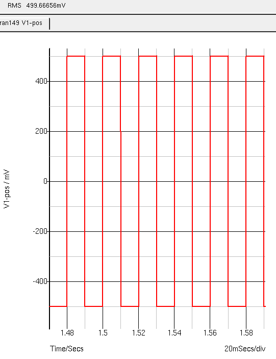
AC square, 1Vtt and 500mVrms
A classic 500 mV rms squarewave. It is 1Vpp. If you do the math the avarage DC value is 0V. Vrms is here equal to Vp, that is a crest factor of 1, and that is 0,5Vrms
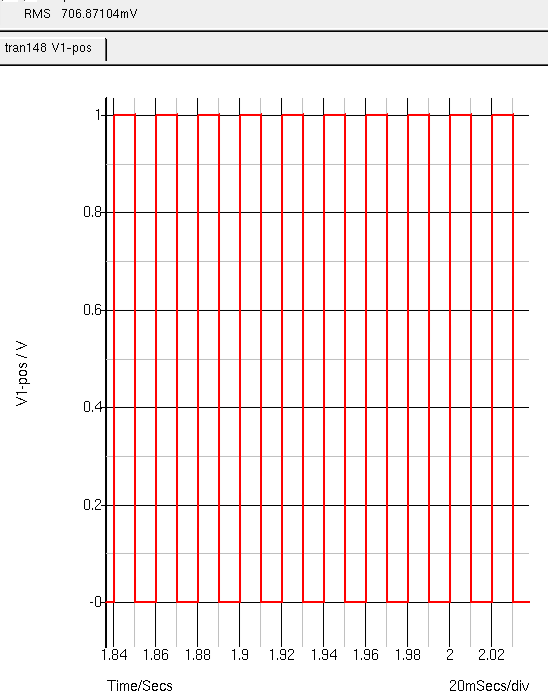
Nu met 500mV offset
This is the same signal but it has a 0,5VDC offset. So still 1Vpp but now an avarage of 0,5VDC. The duty cycle is 50%. The rms value is 0,707 V. The formula is Vp x (1/square root(2)). So 1V x 0.7071 = 0.7071Vrms. The AC voltage needed to heat up a resistor if you used DC.
A AC coupled TRMS meter will show 0,5VAC and switched over to VDC he will show the avarage value, being 0,5VDC. From those two measurements you can calculate the one and only AC+DC TRMS value, the square root ( 0.5VDC² +0.5VAC² ) = 0.7071. But still limmited in frequency and crestfactor.
Some tests I did with a few meters
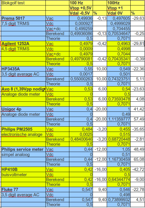
Blokgol f test
You see the problems you get if there is a DC offset. Small rerrors are due to things like not enough warming up time before the test and the generator used for this test. It is not a calibrator (A R&S afgu) . A few meters measure AC+DC. You see that non TRMS meters go wrong above 100 Hz (20-65% and all are from good brands) The AVO8 loads the signal over a 50 Ohm load so much it drops 35% in amplitude. No problem if you only measure mains voltage. An “AC” signal that goes from 0 to +1V is for a diode the same as a DC value. The analog meter only notes the peaks and is slow enough to hold it there.
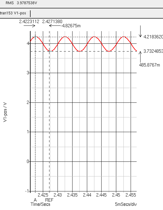
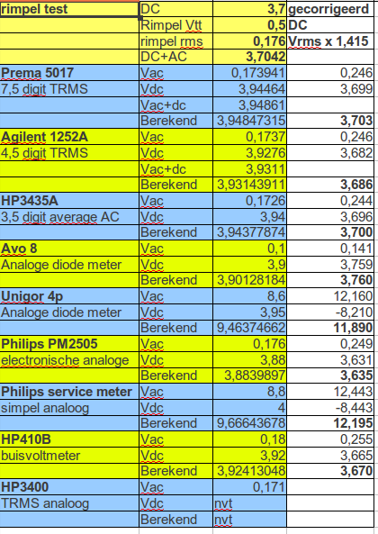
DC met rimpel
While repairing many people only use a DMM to test the powerrails. This is a DC voltage with an AC ripple. The meter measures the avarage DC value so the DC value showed will be influenced by the ripple. So that is why it is better to use your scope. Let’s do some tests. The ripple is not a sinewave, more a sawtooth but lets not complicate things and use a sinewave. I use a 3,7VDC signal with a 0,5Vpp ripple.
The correction will be: DC – ACrms x Wortel(2). So 0,173941 x 1,414 = 0,246V . 3,95564VDC – 0,246 = 3,699 or nearly 3,7V.
This correction is needed because the way the generator gives its settings. In real life the DC signal is the fixed DC + the avarage AC. But that is the DC we measure. In this case 3,9V. If you adjust this rail to 3,7V using your DMM and do not know about the ripple, you must adjust the voltage to 3,94V. So Always measure the ripple too, best with a scope. If the ripple is low the effect will be small and do not forget, if ripple is right, the value the manual gives is measured with a DC meter, so use that value and make no correction. The same goes for the voltage given in schematics from old tube equiped circuits. The analog passive meters load the circuits so you will measure the wrong value with your modern high impedance DMM. You need to use the value given for a tube voltmeter. (if given)
Rimpel op DC signaal test
Forget the correction in my spreadsheet, that was a check for myself.
Important is the fact you can measure TRMS AC+DC (within frequency range and crest factor) with every TRMS meter and a calculator. And you see some older non RMS (diodes) meters going wrong with this non-extreme signal. But also meters as the famous AVO8 and H-410B doing rather well. (forgetting the AC loading problem)
Bandwidth:
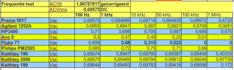
Bandbreedte test
Like a scope, a DMM has a bandwidth. The tests above are done with a nice pure sinewaves from 100 Hz to 1 MHz. The generator gives 0,7Vrms. It is not about how well a meter is calibrated (because in that case I warm up everything at least 12 hours before calibrating) Only look at the frequency response. The Prema http://www.pa4tim.nl/?p=3624 is spec’ed at 2V upto 100kHz and for the 10V range upto a whopping 1MHz. You see the specs do not lie. The HP3400 is an analog 10MHz AC coupled TRMS meter. It is within specs but analog and the generator is not absolute flat over the used range. So do not be to stricked about the results. My very sturdy and good old trusty Fluke 77-III trows in the towel at 10kHz so not even at smps frequencies. The Agilent 1252A, a handmultimeter made for more delicate electronic use as the Fluke, is within the frequency specs. And now you know I like Keithley’s. The 2000, http://www.pa4tim.nl/?p=2440 is spec’ed upto a decent 300 kHz. But like most Keithley specs that is probably worst case. Very worst case looking at the 1 MHz response.
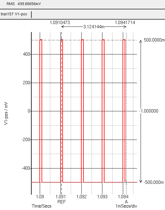
Nu met 10% dutycycle
Je ziet bij dit plaatjes een schijnbare fout in de simulatie software. Het kan immers niet dat die smalle piekjes even veel vermogen in een weerstand opwekken als bij een 50% dutycycle zul je denken, maar toch is het zo. Het negatieve deel warmt namelijk ook op. Als je de negatieve helft omklapt krijg je hier een DC spanning gelijk aan Vp. De rms waarde is nog steeds 0,5V. Dus Vp = Vrms ongeacht de duty cycle. Overigens gaan de meeste scopen daar wel goed mee om. Maar AC gekoppelde TRMS meters niet.
Een puls die van 0 tot Vp gaat bereken je door Vp x wortel(Dutycycle). Dus een 1Vpp puls met 30% dutycycle, ofwel 0.3 ofwel een crest factor van 3,333 is 1V x wortel (0,3) = 0.547Vrms
Met 50% is het 0.707Vrms
Hier maakt de dutycycle dus wel uit. Alle AC gekoppelde TRMS meters gaan hier de fout in. Je moet dan AC en DC meten. Dan wortel (Vdc² + Vax²) = Vrms
Als deze puls nu van -2V tot 2V gaat bij 10% dutycycle dan is Vrms dus Vp ofwel 2Vrms
Bij 0-2V is het dan wortel(0,1) x 2 = 0,6324Vrms
En bij +1 tot +2V is het wortel ( 1+ 0,316227) = 1,1472Vrms
Deze 3 spanningen heb ik getest op verschillende meters. op 1 kHz maar omdat dat te veel is voor de AVO ook een paar op 100Hz als vergelijk.
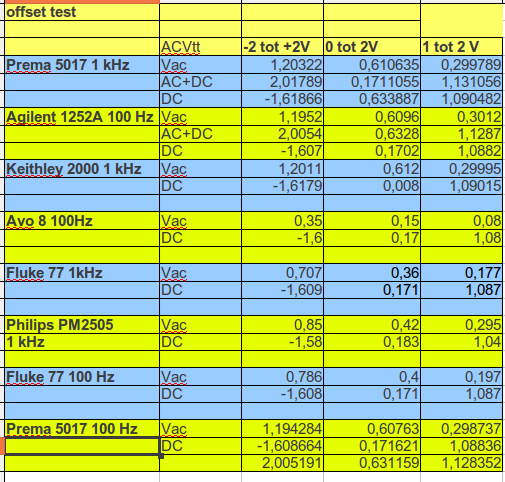
AC, en twee verschillende offsets bij 10% duty cycle
Bij de prema op 1 kHz heb ik AC+DC en DC omgedraaid in de 0-2V meting. De gewone AC gekoppelde TRMS meters kunnen dit toch meten door de AC+DC apart te meten en dan TRMS te berekenen. Alle niet TRMS meters gaan hier finaal de mist in. Totaal onbruikbaar voor niet sinus signalen vooral als de dutycycle geen 50% is.
TRMS is tegenwoordig ook een beetje een commerciele kreet, eigenlijk mogen alleen meters die AC+DC tegelijk meten in mijn ogen TRMS heten.
Hier nog een link naar het zelfde onderwerp van mijn naamgenoot:
http://meettechniek.info/opinie/true-rms-of-een-ware-leugen.html