The black PP3000 is dated 1955, the grey PM6501 is from 1960. Both are Philips.

Philips produced in their NAT-lab 1949 their first transistor. In 1952 Philips made an agreement with Bell labs (the inventor of the transistor). In 1953 they builded a factory and lab for transistors and diodes in Nijmegen. This factory got active in 1954 and 2 juni 1955 it was fully operational and started producing. So the PP3000 is a very early tester. I think they made tem first for their own use. He still works very well. In those days they used alpha instead of beta. So you can not direct compare the test results with a datasheet but who cares. If I want to know if hFE or hfe are good (these are two different parameters) I use a curvetracer.


This grey one is dated 1960:
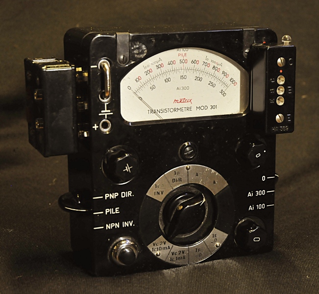
Update juni 2012, through Bert, a Circuits Online reader, I got a copy from the manual of both testers. A nice oportunity to open the grey one and test it. It uses a mix of AC and DC and can deliver enough power to fry a transistor in a flash so be very careful. Putting a switch wrong and you see the magic smoke escaping a BC547. SG is short circuit collector emitter test. If the transistor passes this test, you go to the next step. That is Ice with open base. First the red position, if the needle stays below the red dot but above the blue you go on with the blue tests. This is a leakage test. Not a big issue with modern silicium but very important for germanium. After the leakage test you measure the gain. Alpha in this case. The common base forward Gain (Beta is de common emitter variant)


http://www.pa4tim.nl/?p=4929 for more pictures of this very beautiful tester. The adapters are very handy. They also fit in my Tek 576 curvetracer. This tester is a bit complex to use. It is complete including all papers, warranty certificate etc and even the cardboard box and testleads. It has the french manual and a typed dutch translation. The strange thing is mine has an extra knob that is not in the manual. It is a bit complex in use but it is very accurate.
The whole family together:

The first is a Lafayette EMS-212, I could not find the manual yet. It is a battery checker (upto 12V) can measure current upto 80mA, can measures in circuit. It makes a 5kHz testsignal with harmonics than can be used for signal tracing. (but without the manual I can not find out how) It should be from the early 70’s.
Then a nice Micronata made for Radio Shack, the manual is printed in Japan. This tester works different compared to the the others. It is a go-no-go tester. It tells you if it workes for AC and DC . The position of the knob gives you a relative value that you can use to match transistors. The transistortester is an oscillator. The active part is the transistor under test. It has a transformer and a neon light. The knob is the base current, you start at zero, that is the max base current and saturates the transistor, it is made so that you can not damage the transistor. A bit unusual because we are more or less “programmed” to turn knobs CW while testing things. The neon light lights up telling you the transistor is switched on. Then you turn the knob CCW until the light is most bright. That is the maximum AC gain of the transistor. (at that frequency, beta decreases while frequency increases).
There is an output to hook up a scope to see noise and amplification.
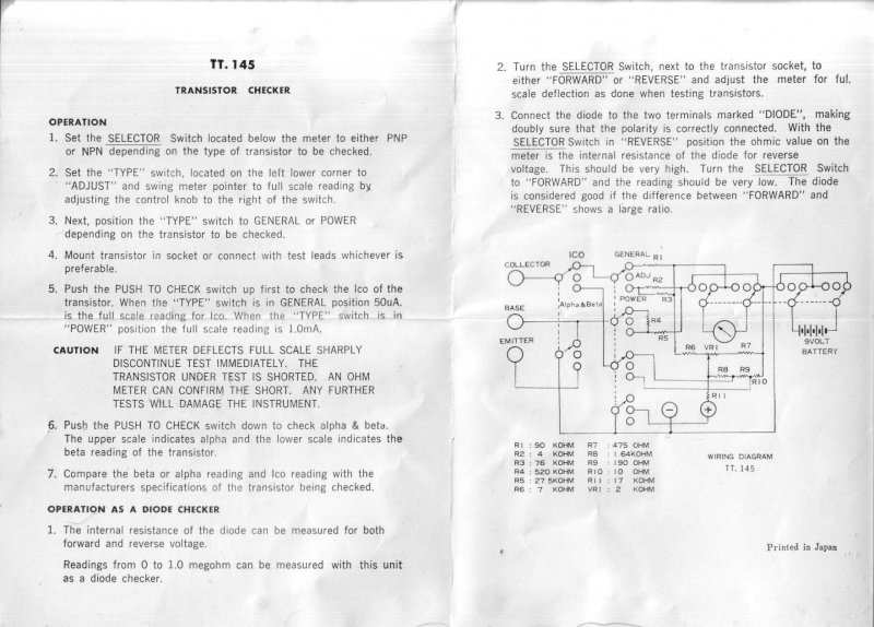
The third a TTC C3022, a Japanese tester, It is sold under several names. like Eagle International TT.145, TTC C3022, Alcron 22, Noris HM-70 and Reace LB-1.
I restored that (more or less) after II found it. I only had a picture from the inside and mine was missing a lot of parts and wires. I did not have the manual and schematics at that time. A Circuits Online member had one and made some pictures and measured values from parts so I could make it work. Later I found on circuits online a scan of the schematic: