I often repair instruments without service doc or schematics. In that case, sometimes the only way to find a problem, is to test the components. I have a programmer/reader that can test many 40 and 74 logic ICs, I made testers for voltage regulators, opto-couplers and opamps. For other IC’s I used a breadboard.
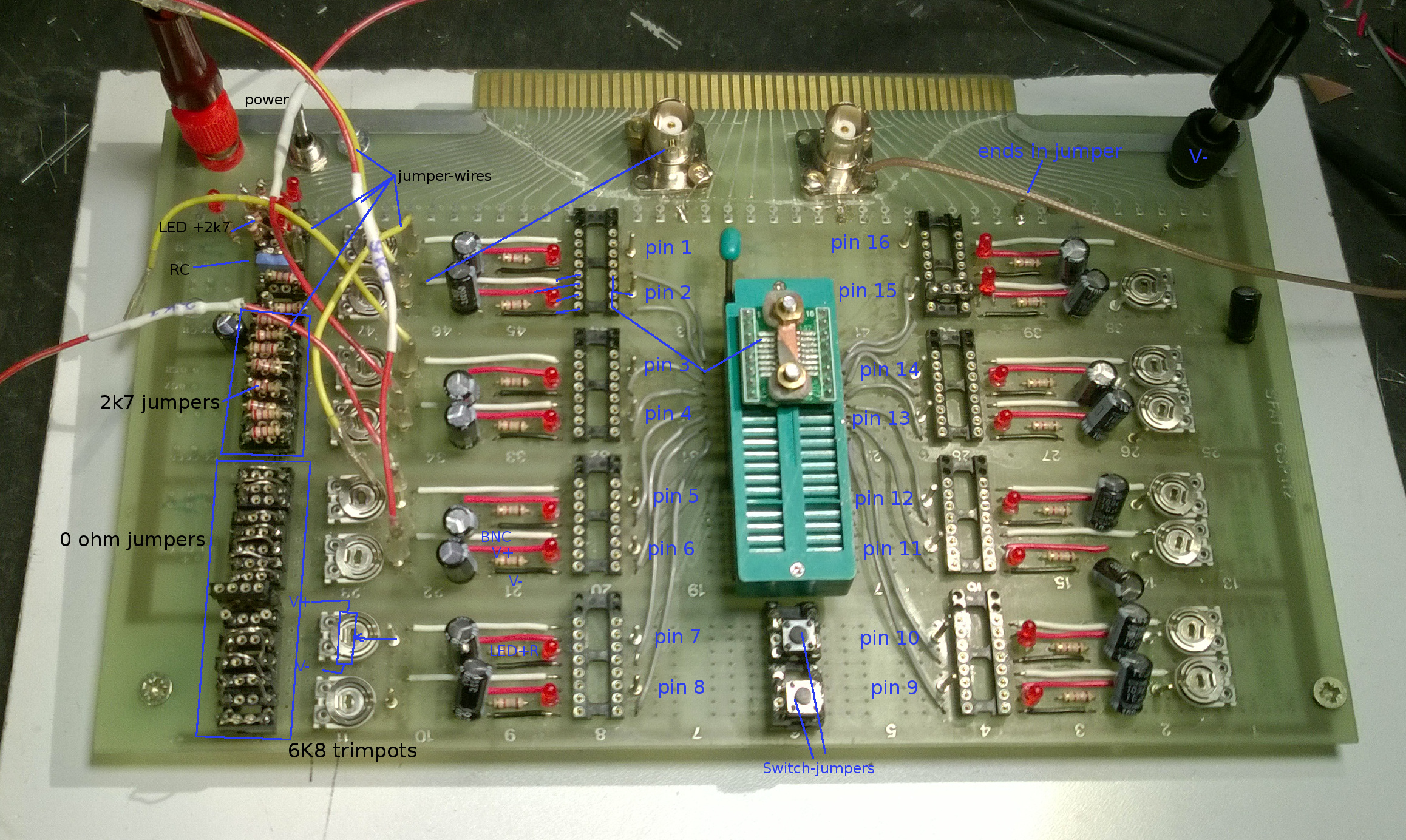
But that was far from ideal. Wires pop out, bad contacts, a lot of parasitics. The fixture I made is for IC’s upto 16 pins. Every pin of the DUT goes to 4 pins of a IC socket. 4 pins opposite of the latter are connected to V+, V-, a BNC, and a LED. I made jumpers to bridge 1 of those opposite pins to the pins connected to the DUT. I made jumpers that form a short, jumpers with a resistor, switches etc. When needed I can make other types. The trimpots are connected to the power rails. The wiper is connected to a pin. I made some jumper wires to connect the trimpots pins to the pins next to the IC sockets.
I placed some IC sockets to the left to store the unused jumpers. 1 of the BNC’s is connected to the white wires. The other BNC has a piece op coax that ends in a jumper.
To use it, I take a datasheet, connect Vcc and Vdd with the use of jumpers. Inputs go to the BNC, trimpots, V- or V+ , outputs to the leds or for instance a resistor to V+ or V-
I note the settings and how to test, for future use. Most IC’s are things like 74/45/40 logic IC’s, opamps, analog switches, transistor arrays.
I made a second one inspired by tubetesters:
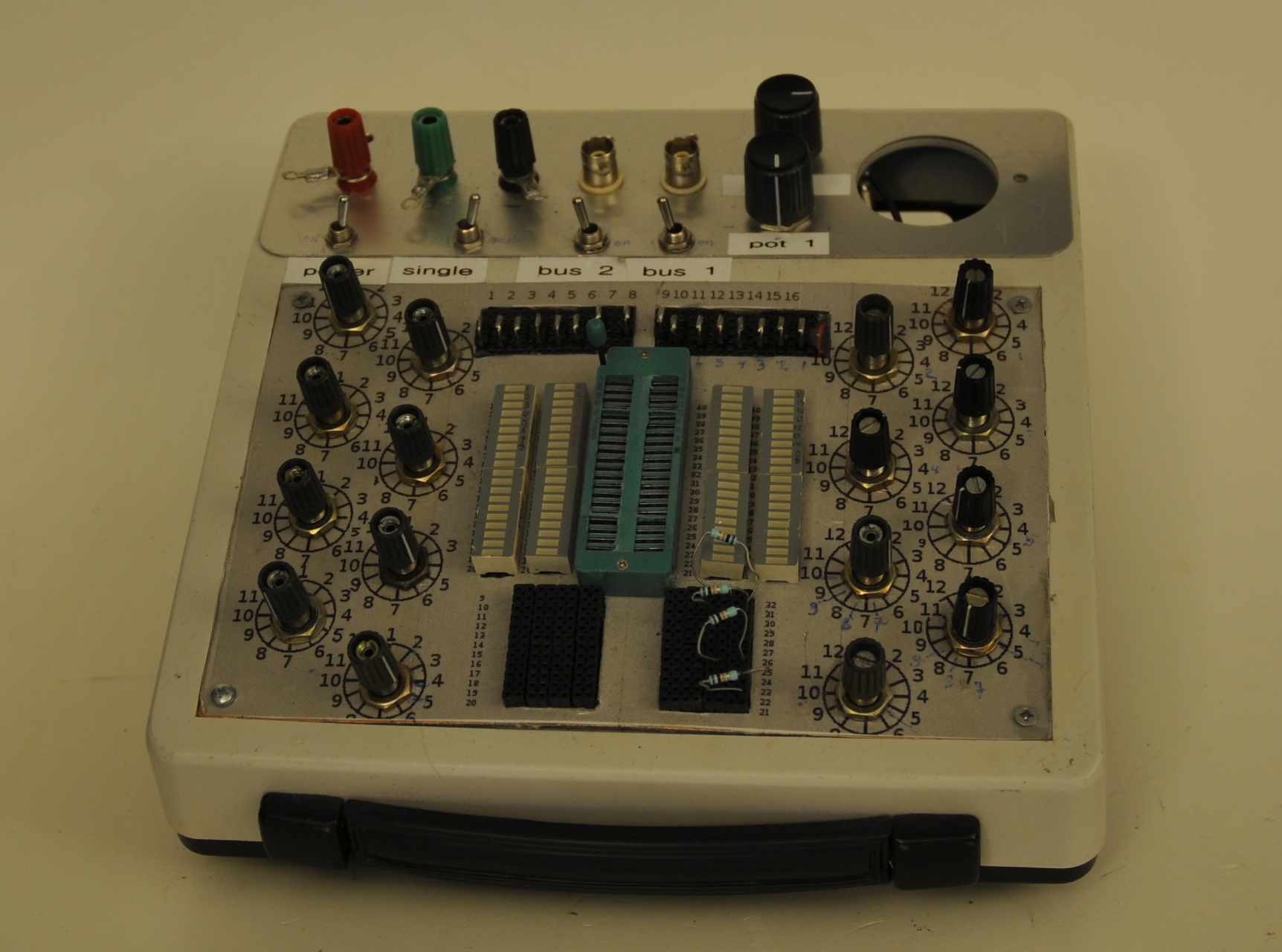
The knobs have 12 positions.
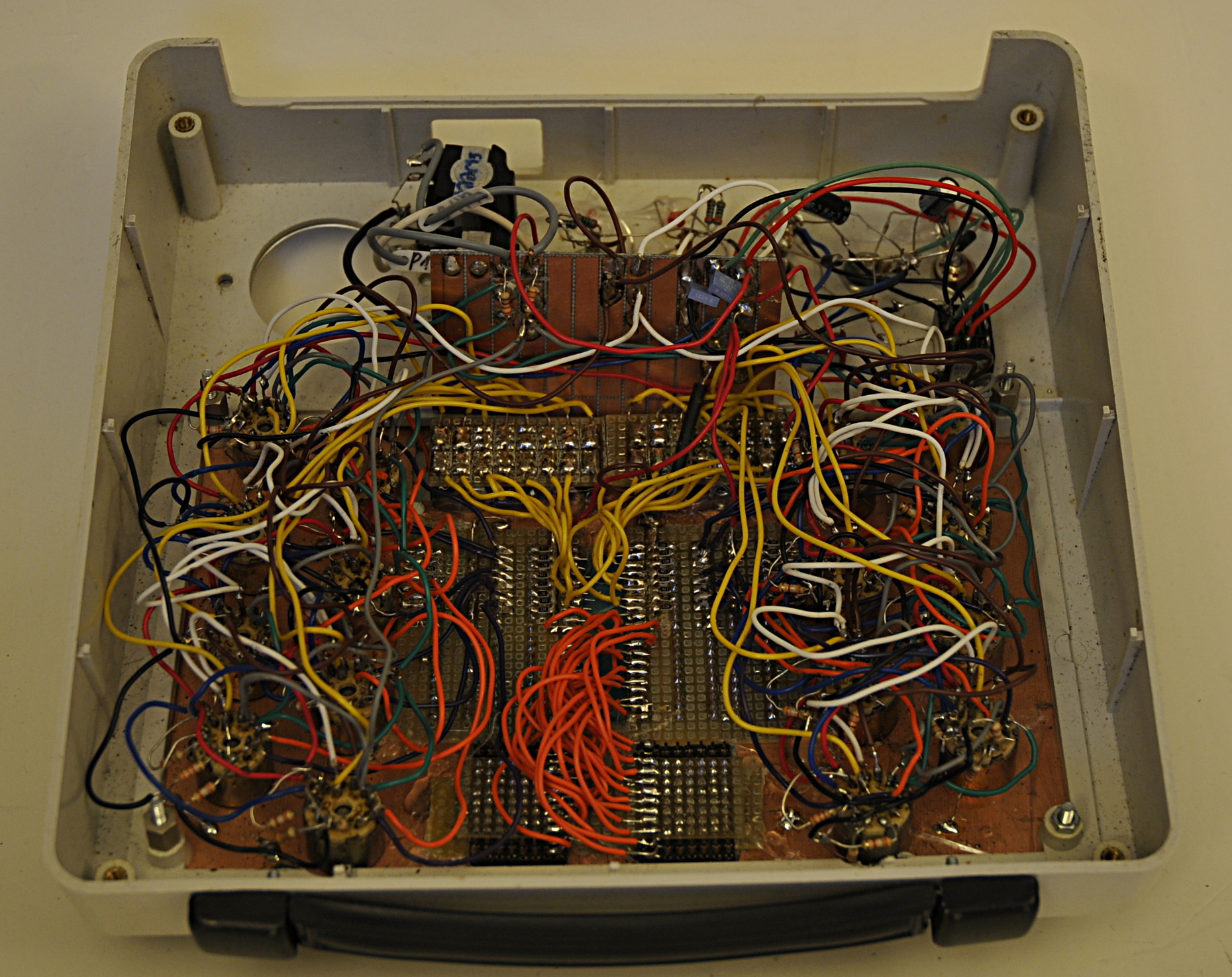
Spaghetti: