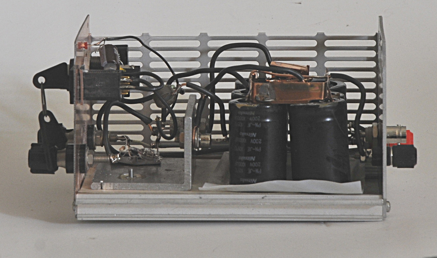
The guts of the beast, it looks so innocent.
It is always handy to have a device dat is able to deliver a lot of current in one time. You can use it to zap nicd’s, test some components, spotwelding batterys, test inrush protection ,blow up cheap Chinese multimeters, of or like me, test transformers and inductors . In theory, f.i for spotwelding you need a lot more current and thus capacitance, and thicker wires etc
I have a few other pages about testing inductors. At first sight they do something similar but that is not entirely the case. The device on this pages dumps a whole lot of current, but just one single time. My other saturation tester pulses with a certain frequency and you change dutycycle until you see saturation. So you know something about it’s behavior at a certain frequency and dutycycle.
The zapper on this page is pure a current test. You can see the core of an inductor as a selfinductance multiplier. But by witch factor depends on the current. The current produces magnetic fluxlines in the core-material. But the core can not handle an infinitive amount of flux. By dumping a lot of current in one time you can see how the inductor and for most the core react to that. An inductor likes to handle a constant current, they do not like changes in current and “fight” that. You see that in the first part of the curve. The current increases over time until the point it gets to much and the core saturates, from that point you see the current rising much faster.
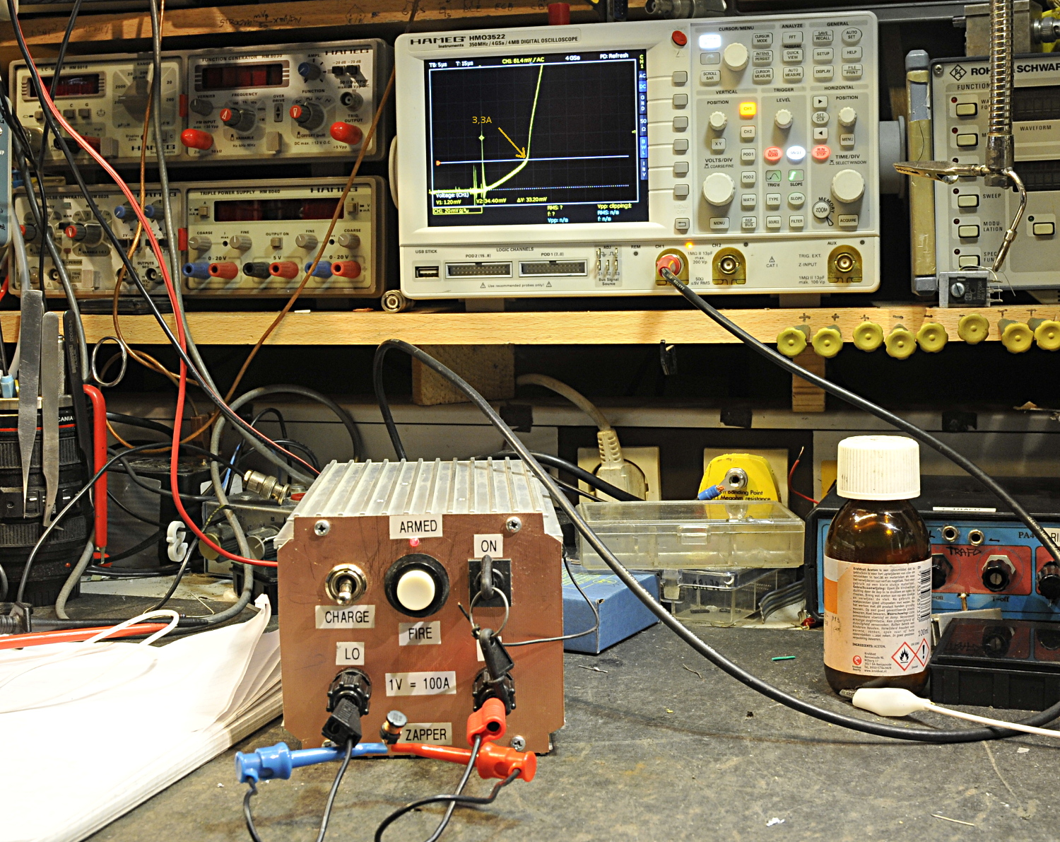
In action, testing a very small inductor from a buck converter
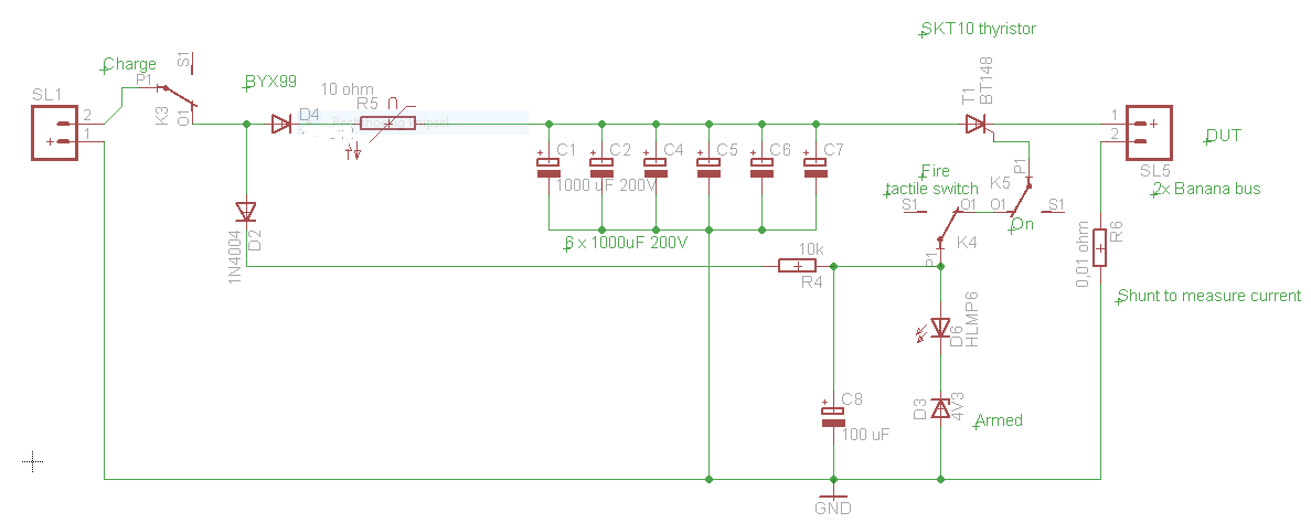
This is important to know because it still more or less works after saturation but it can get very hot. The amount of current increases, that sounds good, but the selfinductance decreases and so degrades an important function of the inductor. To store and “relocate” energy. This is very important for an inductor in SMPS’s. You see the small inductor on the picture above. It saturates here at 3,3A and is not fried. If I short the output of the zapper and feed it 20V it delkivers 354A. To much for the used SK10 thyristor. My caps are 200V and together 6000 uF. I will need a very heavy thyristor if I wanted to use it at 200 VDC.
By dumping a lot of current in one time the influence from frequency / dutycycle is minimized. But also the risk, it is very easy to burn it if you increase the dutycycle to much and to long. You must react very fast if it goes in saturation If you do both tests you can compare the results and get a better idea about the inductor. I combine this with several other tests if I need to design an inductor or transformer.
You can do more with the measured data. You can use it to calculate things like selfinductance. Some formula’s
Q = CV Full power that would be 0.006F x 200V = 1,2 Coulomb
V = L(delta_I / delta_T) for instance to calculate L (L in Henry, Time in seconds, I in Ampere. In the picture above it would be something like 20V = 100 uH(2A x 0,00001s)
Vrms = 4.44 x F x N x A x B B=tesla (datasheet), A= meter2, N = turns, F= Hz This formula is not direct usable here but it a useful one for other test and measurements.