Huge but stuffed with functions
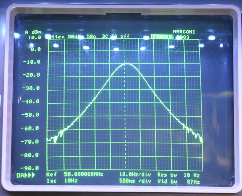
This SA covers a full span sweep from 100Hz (!) upto 4,2GHz. The Resolution BandWidth is 3Hz, that is very narrow. Besides that it has a 0,025dB resolution and the counter has 1 Hz resolution. With my 10MHz standard connected that is a very nice function. There is a GPIB interface and a RGB output for a color monitor. The amount of functions is rather high for such an early digital SA. Things like log/log sweeps, 2 markers, trace store and a lot of buttons that makes it very easy to operate. Here a picture with 10Hz RBW and a 10 Hz/div span.
High resolution
The display is a TV style CRT. It is big and easy to read. It can display 2 traces with different settings per channel.
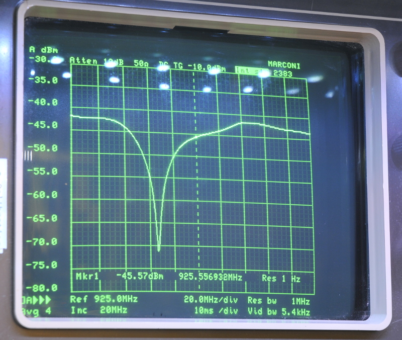
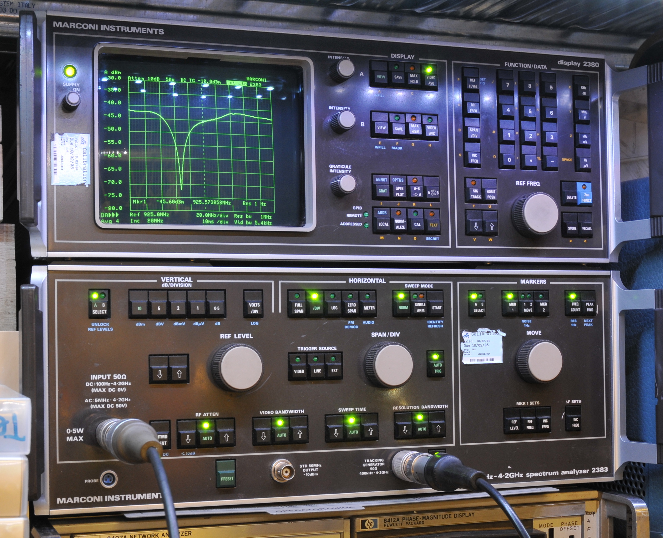
The tracking generator
It has a build in tracking generator with adjustable output and very flat over the whole span. The picture above is the return loss from antenna measured with a HP directional coupler
The CRT
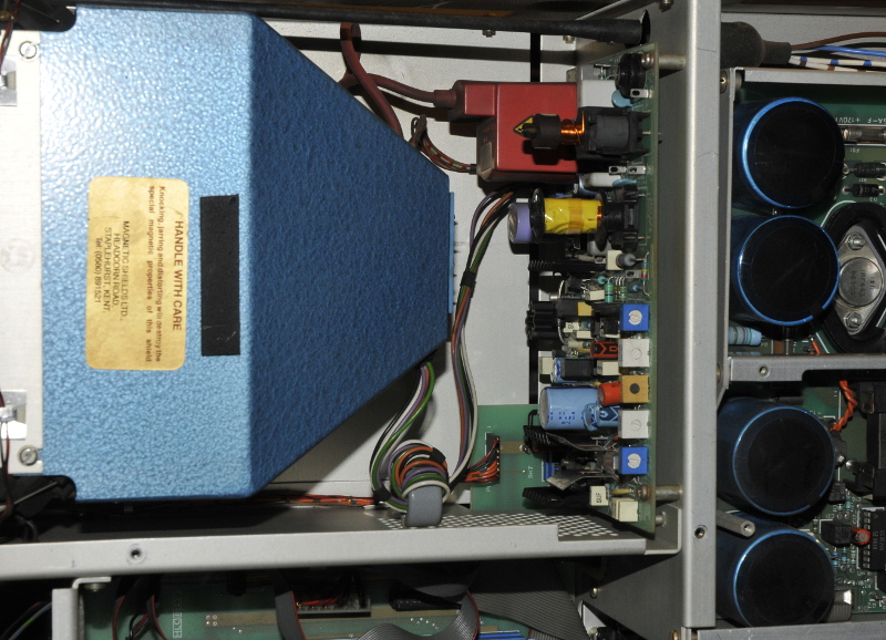
It did not work so I had to repair it. I had the service doc for 2380 display+PSU unit but not for the 2383. There was no trace. The first thing to check is the PSU. That thing is huge and is spread over 4 boards. Two are back to back in the display unit, there is a small filter board and the high voltage board. In the analog/RF unit there is another PSU board.
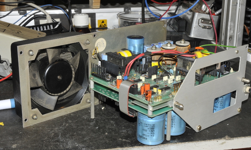
2 Power supply boards mounted to the backpannel.
Both back to back boards with huge caps and over 50 testpoints.
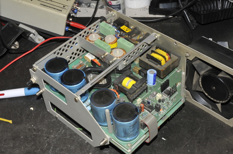
The main power board
Besides a dead transistor in the main power unit there where a lot of bad caps. After that the trace transforms in something that looks like it is come from the game Minecraft. There was a squareblocked looking trace. That improved after replacing the caps in the 10 MHz unit and the logamp. After replacing over 50 caps (most the same brand/voltage/capacitance) it is gone for most of the time. Replacing the rest of the caps is a lot of work I will do somewhere in the future.
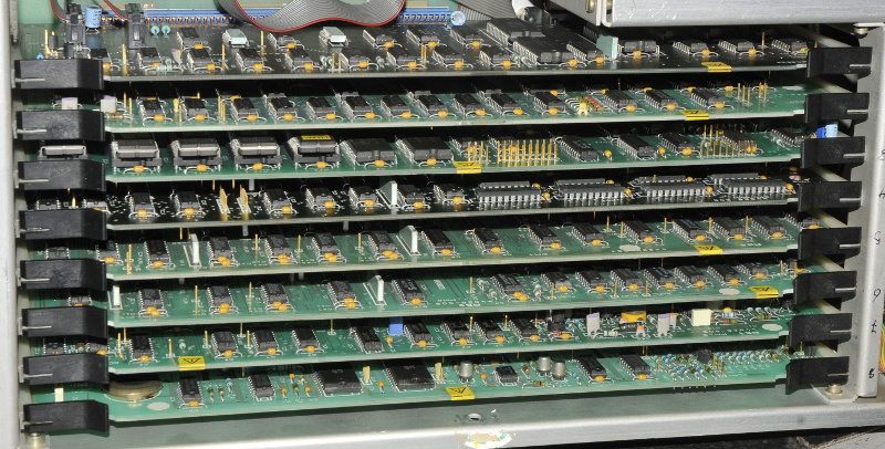
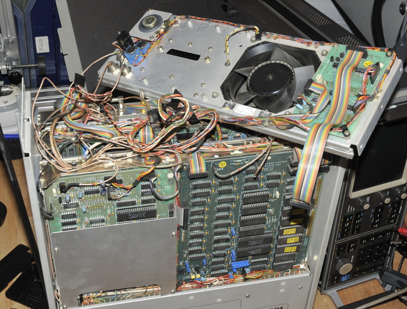
The digital section of the display unit.
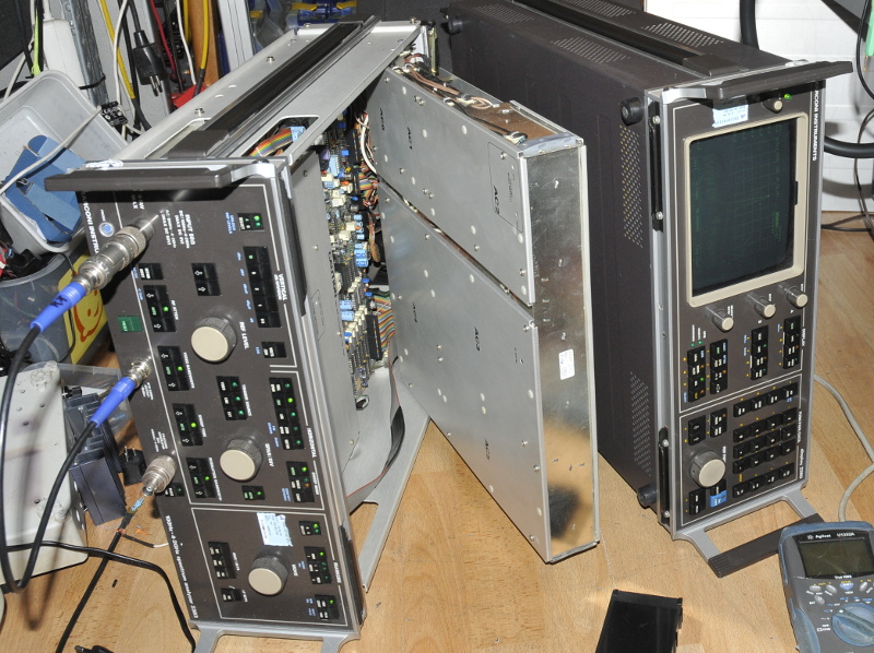
The problem is that both units must be coupled by two short cables on the back. The main PCBs are mounted on pivots and swing out. Without the longer cables the only way is to set them like in the next picture.
Adjusting and testing
Removing the PSU from the RF unit involved de-connecting a lot of connectors.
Removing the last PSU