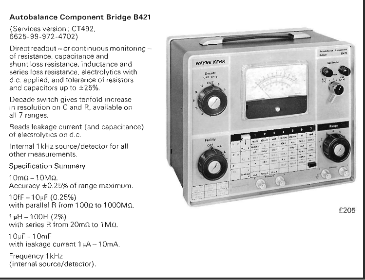
I got this LCR meter from a friend who bought it. But it did work like it should. Because he needed a LCR meter I gave him my marconi TF1313.
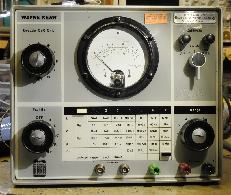
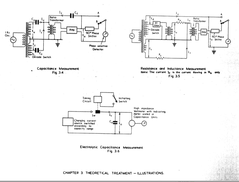
It was made for the navy and is based on the B-421. It has very good specs and some features that made it rather unusual . It is direct reading and autobalancing. They used the error signal from the bridge to show the value measured. Most bridges or LCR meters use D and Q but not this one. If you push the black button it is direct reading Rp for capacitance and Rs for selfinduction. Besides these things it can measure electrolitic caps upto 10mF. A huge value in the 60’s. It uses DC for this mode. Beside two banana sockets to connect your component it has two guarded bnc connectors.
This works a bit odd. You have to switch to range 4 , set the right top switch to zero and then zero the meter. Then switch it to operate . Now connect the cap and push the black button. And if you now push the black button the meter starts to travel and when it stops you can read the value. Then you can switch to range 3, 2 or 1, push the button and read the leakage current with upto 2 uA resolution.
They made a very nice tabel on the front that shows you how to set and use the knobs. There is a black and a green scale on the meter and the tabel uses the same colours. A bit confusing is the way you need to read the meter. In black the range value in the tabel is the full scale value. So 10 in the 100 uH scale is 100 uH. But if you chose for instance the 10 uF range the scale starts at 10uF and must be read from right to left. Besides this there is a sort of magnification knob. If you have a 8.64 value the meter will read 8.6 and you can guess the rest. If you now switch that knob to 6 and the meter then shows the 4.
But as said, it did not work. I played a bit with it. I did not have the very obscure 4,5 batteries. So I used a lab powersupply. I found out the bridge did work more or less as I used 6V instead of 9V. Time for some surgery.
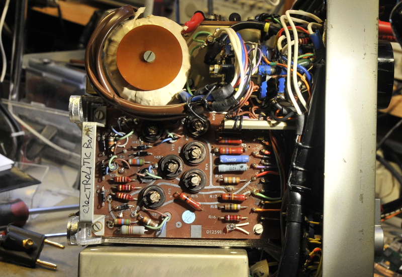
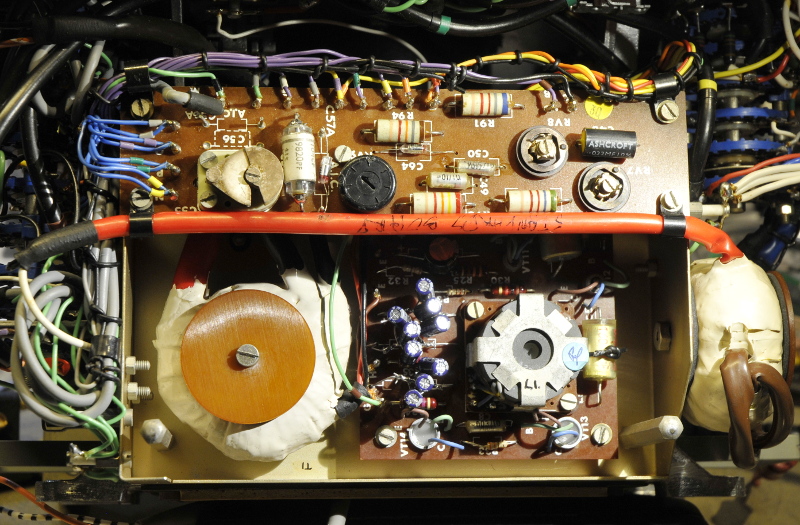
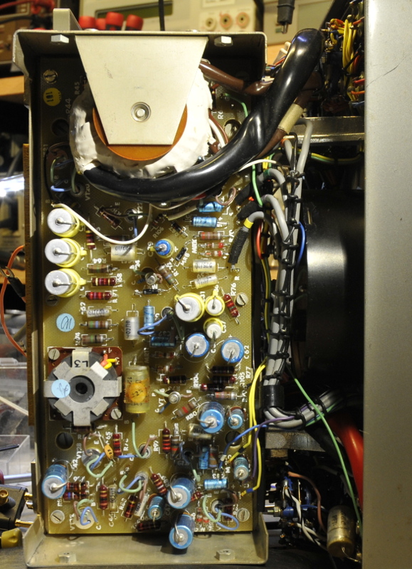
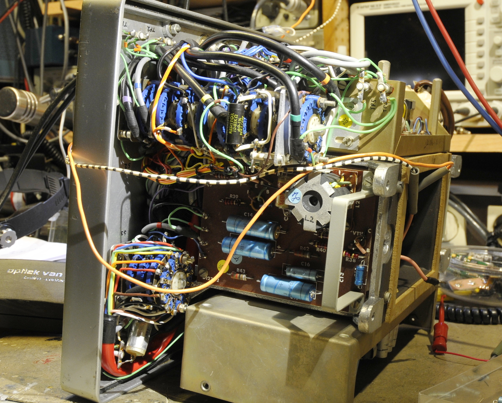
There is a lot of electronics in side (for a bridge). It is well build. It uses a mix of germanium and silicium transistors. The oscillator is LC based. It is very stable. I adjusted it to 1000.05 Hz and it stayed there within +/- 0.05 Hz . Very impressive. But then it first had to oscillate. The scope showed only a repeating ringing signal. I replaced the composite resistors because they where outside the specs. Then bridged a part of the feedback and this made the oscillator to start. The real problem turned out to be a 64uF 10V cap between the output stage and bridge transformer. After replacing that, it worked perfect again.
While checking the modes and ranges it showed a strange problem in one of the C ranges. I found the cause after tracing the signal with the scope. The C mode standard cap had a bad soldered pin at the place the pin is soldered to the cap. After that all went well and it is working again within the specs.
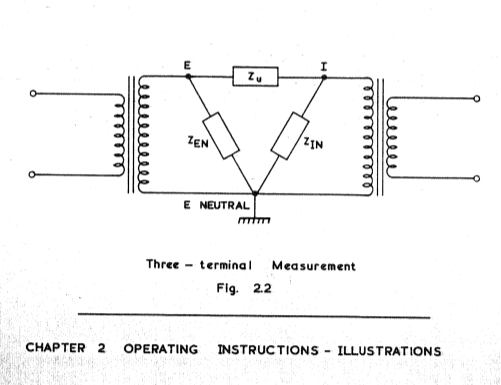
This bridge uses two transformers. This is a very stable construction.
It uses a guard for 3 therminal measurements
A spec sheet: