
This is a Fluke 5101B with the wideband option. It failed calibration (done by Fluke). This is not mine but a commercial repair/overhaul I do for the company that owns it.
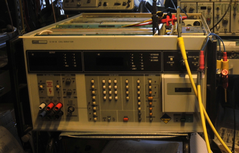
This is not an easy way to acces testpoints
This calibrator is rather heavy and there are lots of pcbs inside. Most are shielded on both sides. To find the faults and adjust it, you really want an extender and have to undo most boards from it’s shields.
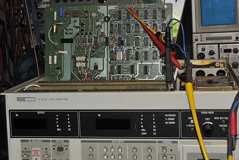
With an extender it looks like this
It will look like the picture above with the right extender, to bad my Fluke extender , or one of my other extenders did not fit. Anyhow, with the right tools and some tricks it can be done. I lift the board, hook up a probe (sometimes I solder a wire or probe adapter to the pcb) and insert the pcb including probes. I use things like shielded testwires made from triax and long flexible probe extenders.
Some readers wonder why I have a number of 6,5 and 7,5 benchmeters, well, that is for jobs like this one. Never trust 1 measurement and 1 meter. If you have a wrong reading there are three options, a fault in the circuit, a wrong test setup or a problem in the meter/probes etc. In that case I first remove the probes, then connect them again and note the result. If it is the same I connect a second meter. If results are still the same, I know it probably is the instrument under test.
To repair this sort of instruments is not that easy, you need gear that is a few magnitudes better as the patient. You need the right service manual . Things like this calibrator are often made over many years what results in several revisions. In this case the manual was from a later model. That does not make it easy. The power amplifier for this older version is very different. That makes it a nice puzzle and with some reverse enigneering it was not a big problem. But it takes more time.
Often you need a lot of rather special testgear, cables and standards. It is even more important that you know how to use that gear the right way. Things like the Seebeck effect, thermal and mechanical stress, temperature and relative humidity etc, are trying to get you on the wrong track. But you also need to recognize “faults” in the manual. (by reading the schematics and some calculations or alternative tests) It is a lot of work, but for me this sort of projects, is what I like most. Not many companys do this sort of repairs today because they only look at the amount of hours used. It would become to expensive. (relative speaking, a new calibrator is still many times more expensive). For this sort of projects time is not a good base. It takes a lot of time to do it right. I crosscheck my instruments very often to be sure there is no drift. (often befor and after every step) Many measurements are done a few times, with different testgear to exclude faults. It is important you know how to operate it, be familiar with the theory of operation and know how to do performance tests. This all takes time.
Most times these project are done in a few steps. First a test to find the problem areas. So that means learning to operate it, and verify every function. It helps in this case, there was a fresh calibration rapport from Fluke. It was calibrated with (among others) a HP-3458, the king of multimeters , and a Fluke 732B. The wideband option was tested with a not specified standard labload (it needs a 50 Ohm, RF suited load). Most cal results where given as 5,5 digits. The 5101 has a driven current guard and a separate voltage guard. The DC current ranges below 200mA were out of tolerance and some ranges stated as unstable. But not specified how/what. The cal rapport stated all measurements were made without the voltage guard connected. Strange, they made an active current guard just to make it look good in the brochure ?? 😉
Because the comments were very general I had to find out the real problems myself. The problem was that it was not concistent. Sometimes it was stable, other times not. Very difficult to find intermittent faults. But I was lucky, I was checking some things in the schematics while waiting for it to warm up. I heard pooffff and some smoke came out.
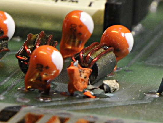
a tantalum with air as dielectrium
This was the cause, a dead tantalum in the filter from the 15V that feeds the most important part of the instrument. After this, a dead capacitor in the poweramplifier and fixing some other things, the output was stable. Not big problems on their own but all together it becomes cummulative.
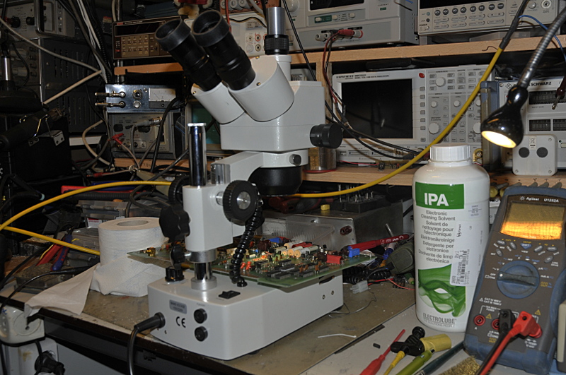
Checking solderjoints
It is not my style to only repair. What I do with my own instruments, I do here too. I try to prevent possible future failures. One of the ways is looking at solderjoints and parts with a stereo microscope. Besides that I clean the whole inside of the instrument and the pcbs. In this calibrator the airfilter on the back was missing and the boards nearby were far from clean. Dirt is something you do not want in a calibrator so I made a new filter. (3D printed)
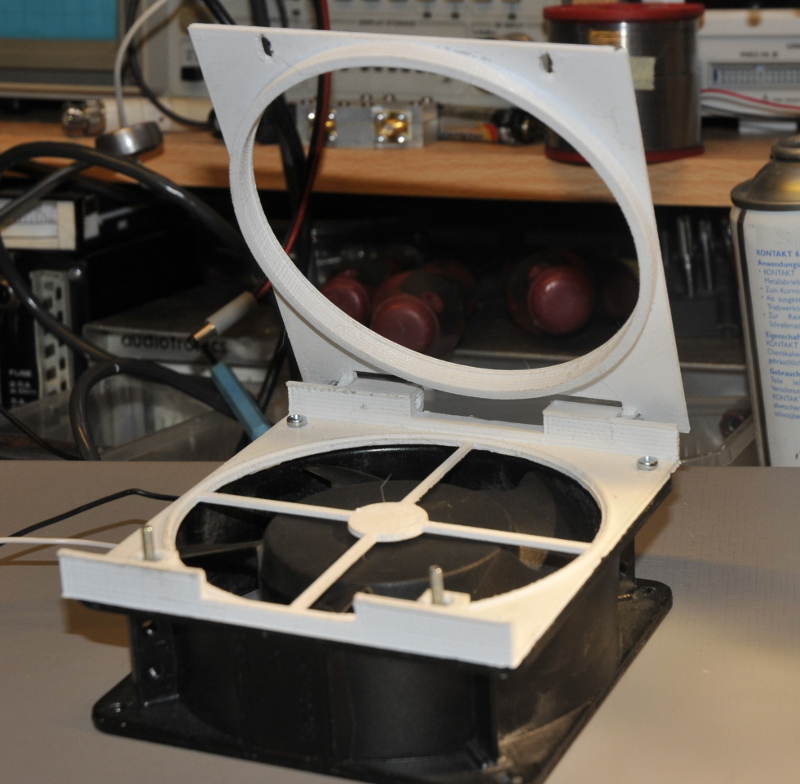
3D printed filterholder
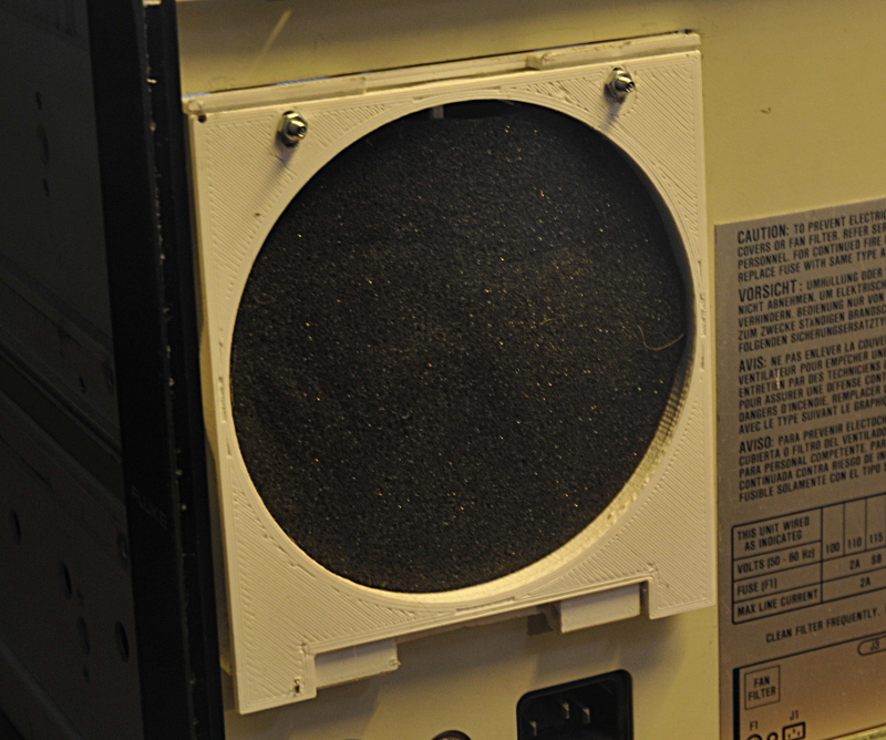
mounted with a foamfilter
Another source of problems was at the board that has the range switching and resistance standards used for current and resistance calibration.
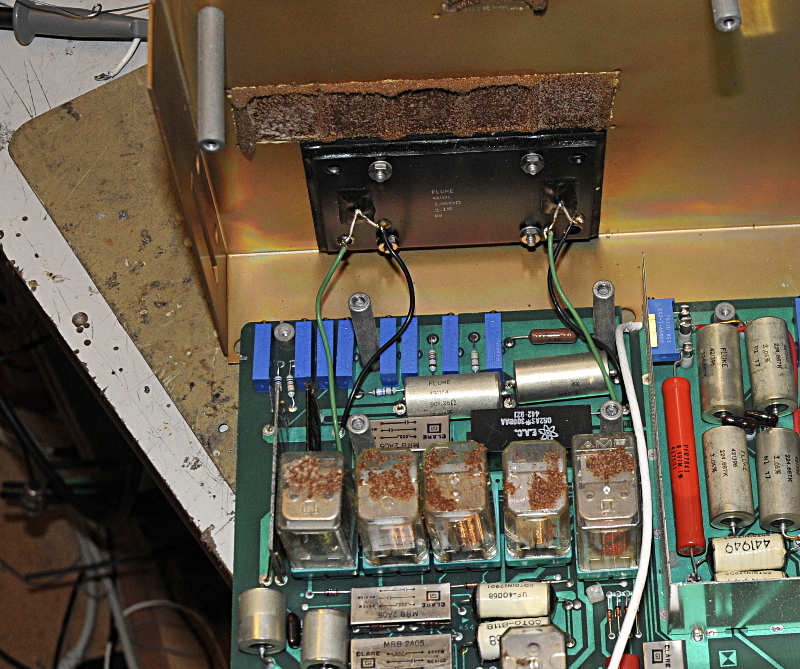
yuk, this once was foam
That braun stuff once was foam to press the relais in the sockets. The pcb and relais were sticky from the oil like resisdu. It was a lot of work to get it clean again. I also placed new foam.
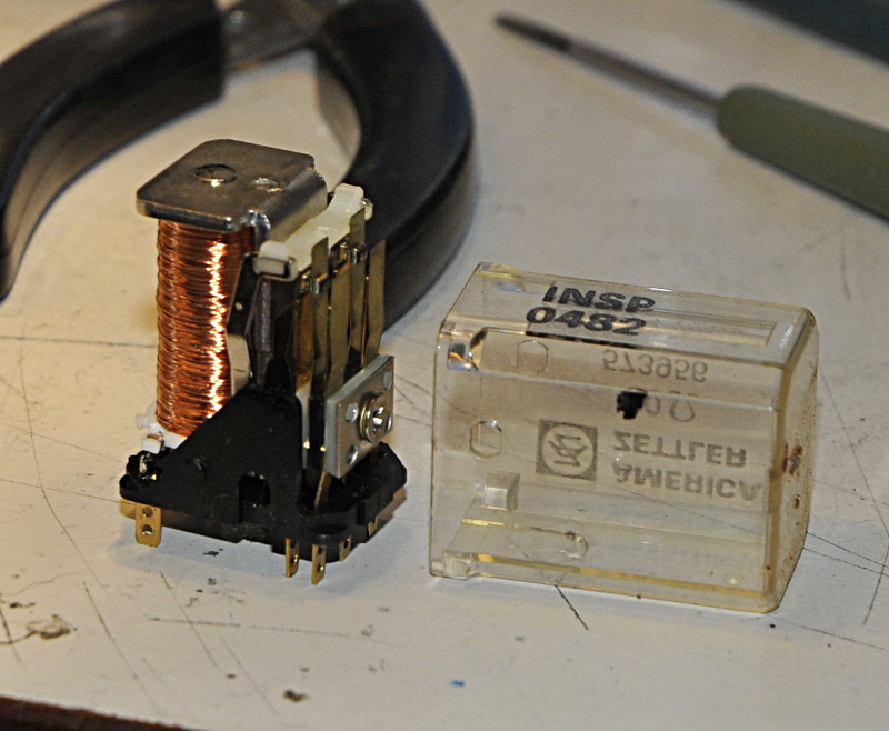
relais cleaning
I cleaned the inside of the relais to be shure. In the resistance mode I had noticed the results were not always the same after switching. After cleaning of this board and the relais it was stable.
Last part of the project is a lot of work and time consuming; calibrating and adjusting. You need to understand what the manual states, warm up everything (at least 2 hours but often more, my instruments are powered 24/7 during the project.), build the test setup for the every step in the process (one of the many, many steps, you easy go over 100 measurements) and then measure and adjust. Often steps need to be repeated several times. Or again in a later stage.
While adjusting I found a bias that was well within tolerance but I allways adjust to check. The 10 turn pot caused allmost no effect. But some calculations I made from the schematics showed there should be a bigger adjustment range. There also was a signal related that needed adjusting for zero drift on a scope. This worked but not 100% as in the manual. So I stopped adjusting and went back to trouble shooting. A 450k resistor had become 500k and I found a bad solder joint from a stud holding a hand picked resistor.
After this I needed to check the adjustments and calibrate steps done before.
The final calibration gave no problems, Feedback from the owner reported it was spot on.