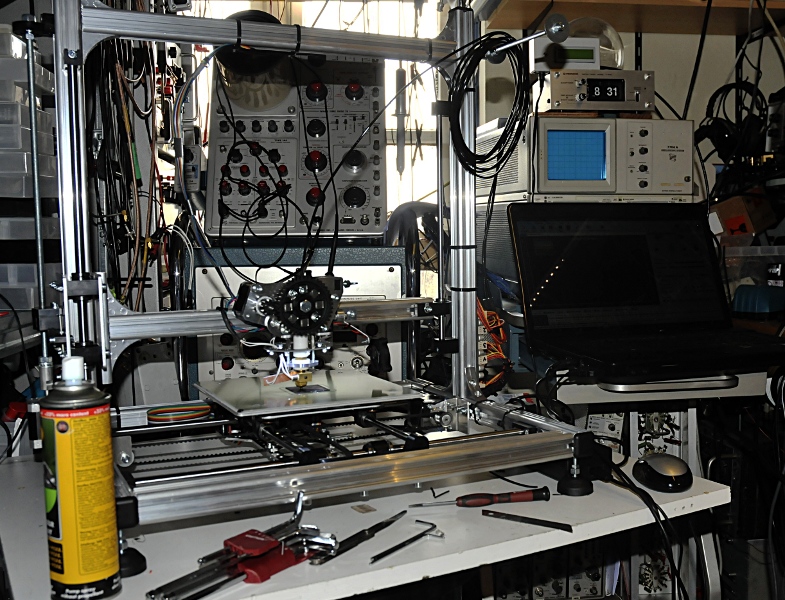
I have build this 3D printer. I want to use it to make cabinets, knobs etc.
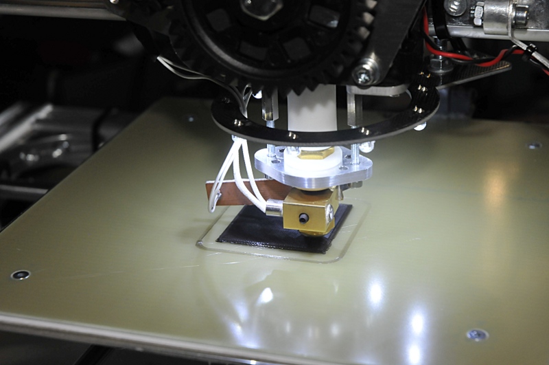
I made some modifications like copper washers between the extruder parts to prevent leaking. The pcb holds the thermistor. That way it is safer , protected and using thermal paste it works better.
http://www.pa4tim.nl/wp-content/uploads/2015/10/printerelectronica2.jpg
The tumbwheels construction was very not handy. I glued the nuts and a washer to the wheels. Now it is very easy to adjust. (update, nuts come of through vibrations)
I use 123D design and some other autodesk apps to desing things and Repetier to control the printer. Update, I now use Freecad, a great open source 3D package with very helpfull people on the Freecad forum.
Update november 2014:
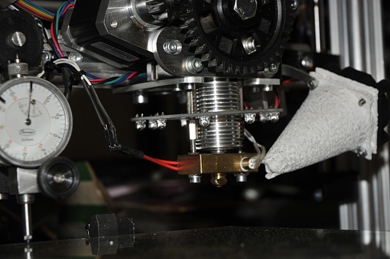
I made a new extruder from aluminum, teflon and brass. Here still without the fan mount that needs to keep the upper part cool in the hope the filament will not jam anymore. The thermistor is now mounted better and safer. I use the same heater but after the electronic mods it will run on 24V, the heatbed too. The extruder uses the (still) original mount. I do not like the filament transport part. But that will be fixed later.
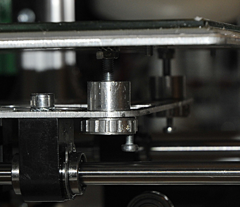
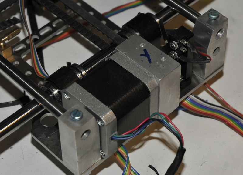
The weak part according many users is the Z axis. To much wobble (mine was not bad) and back-lash. I do not know if the latter is a real problem. The gravity pulls the whole construction down so that takes care of the backlash allready. I did not use a shaft with acme thread. In my opinion you use that for more speed, not for more precision, but I can be wrong. But milling and turning is fun so I made a rather rigit silent block as flexible coupler. not to soft because I do not want the axis to lag in movement and then shoot over after stopping. The spring is to minimize backlash. The motor is mount on aluminum blocks with an extra brass stabilisator between the plates. After everything was mounted the bottomplate and stabilisator were a bit overkill.
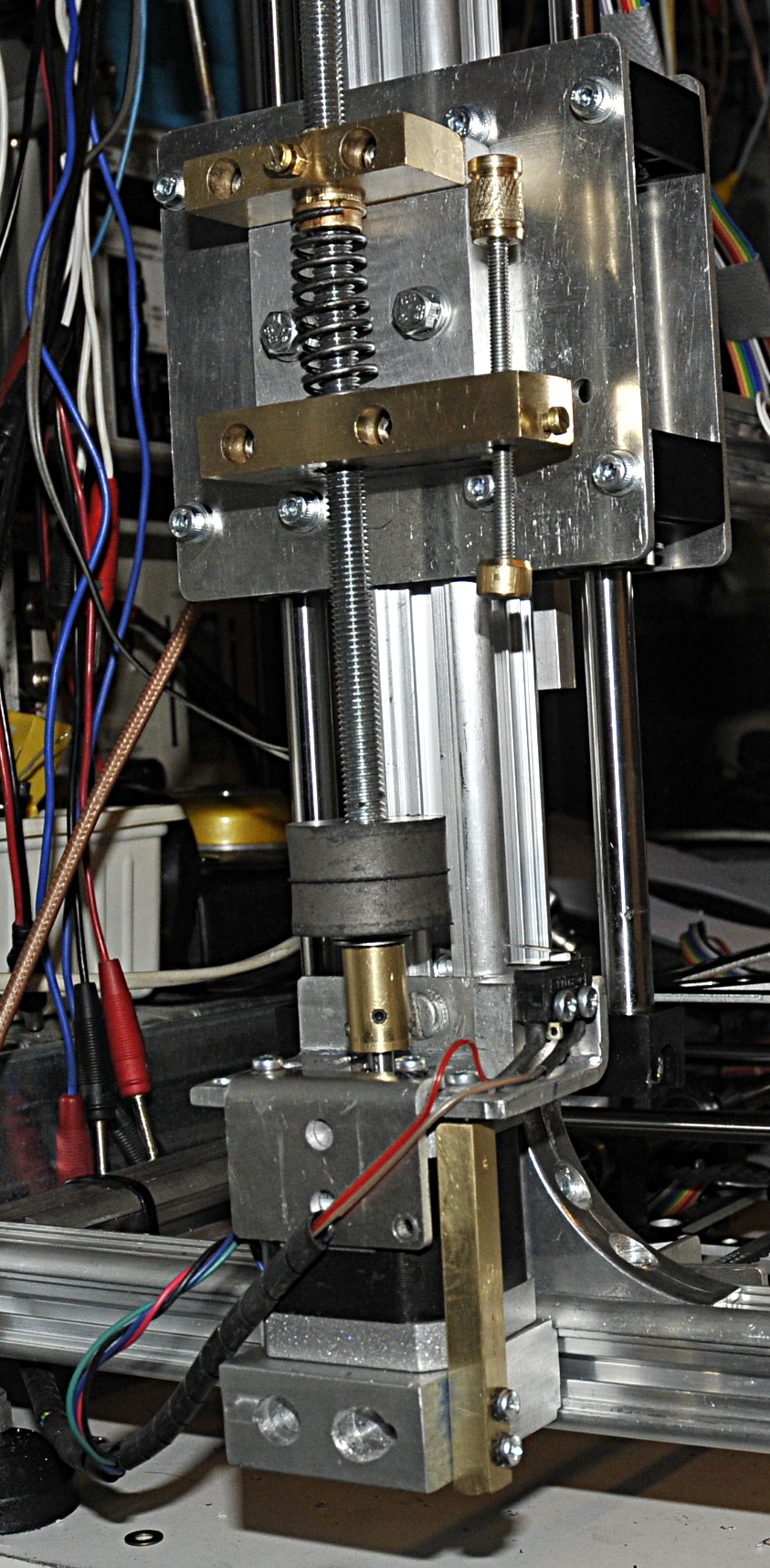
New Z-axis mount
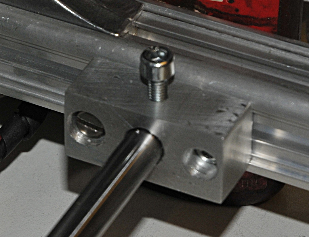
The heatbed mounting was crap. I did not wanted springs because that can give a reaction after a fast move. If the bed stops you want it to stop and not move a bit in any direction due to the springs and small bolts. I made a big nut that goes through bigger holes in the frame.
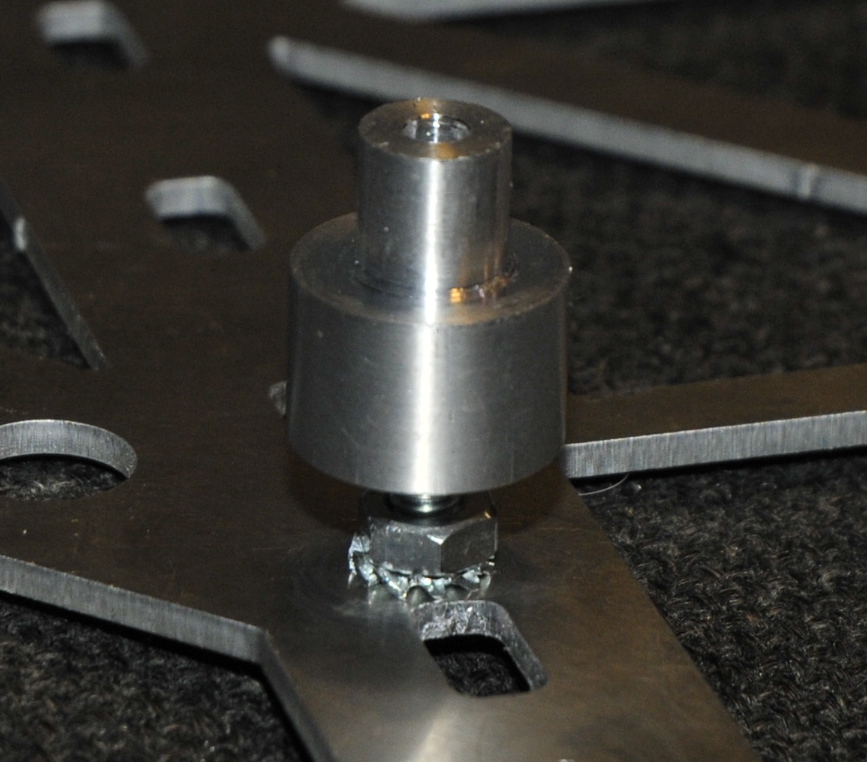
The frame is sandwitched between the nut and a tumbwheel. The wheel is fixed by a pin to the nut. Shims make sure there is no vertical play. (just enough to rotate the wheel with some light force) The wheel has a lock bolt. This way I can lock it without messing up the adjustment.
The mounts for the X axis belt opposite to the motor. The belt runs over a wheel that has 2 bearings and a 6mm shaft. It is made from two pieces 20x20mm aluminum and the one with the wheel is countersunk and mounted with a pressfit in the other.
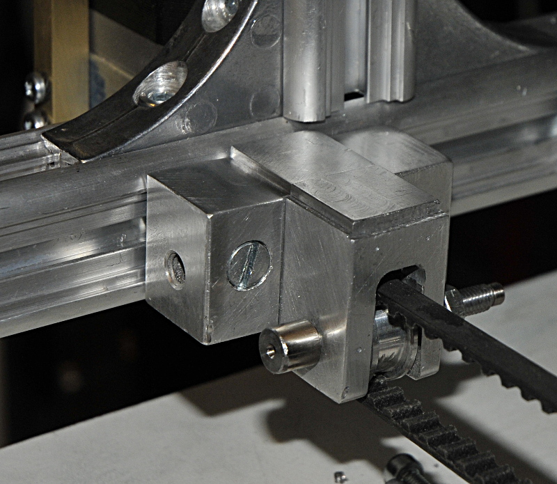
Down here, the new X-axis belt grabber and X-axis end switch adjuster. Also with a locking bolt that does not change the setting while locking. I also made a belt tension mechanism that looks a lot like this. But in that case the bolt you see has a round profile to pull the belt.
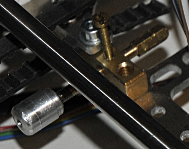
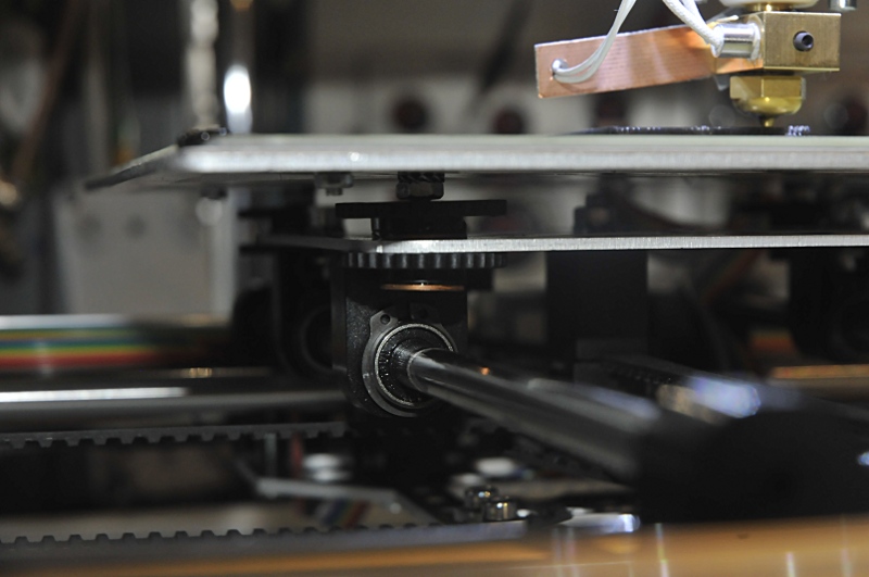
The Y motor was mounted on a flimsy peace of plastic. Putting more tension on the belt resulted in a motor that moved diagonal. Now it is mounted on a big piece of aluminum. The shafts now are on both sides mounted in thick aluminium blocks. The bolts on top remove the last freeplay. This makes the whole construction very rigid and stable. Just touch the shafts on your printer and look at the heatbed movement with a micrometer. Not a pretty sight. In my opinion more important then an other Z-axis construction. Think what the vibrations of a fast moving bed will do with the frame.
The other shafts:
Now the electrical part..
Oktober 2015:
Finaly had time to complete the project. The extruder became a mix of the original and some new parts.
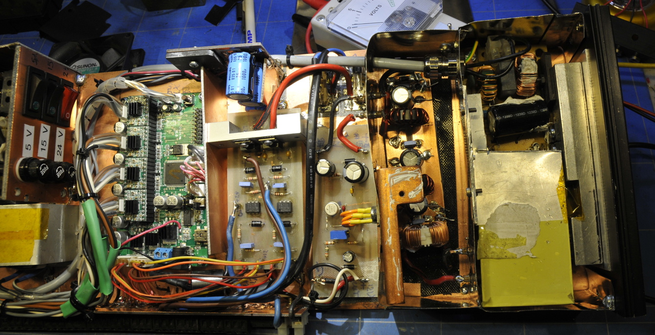
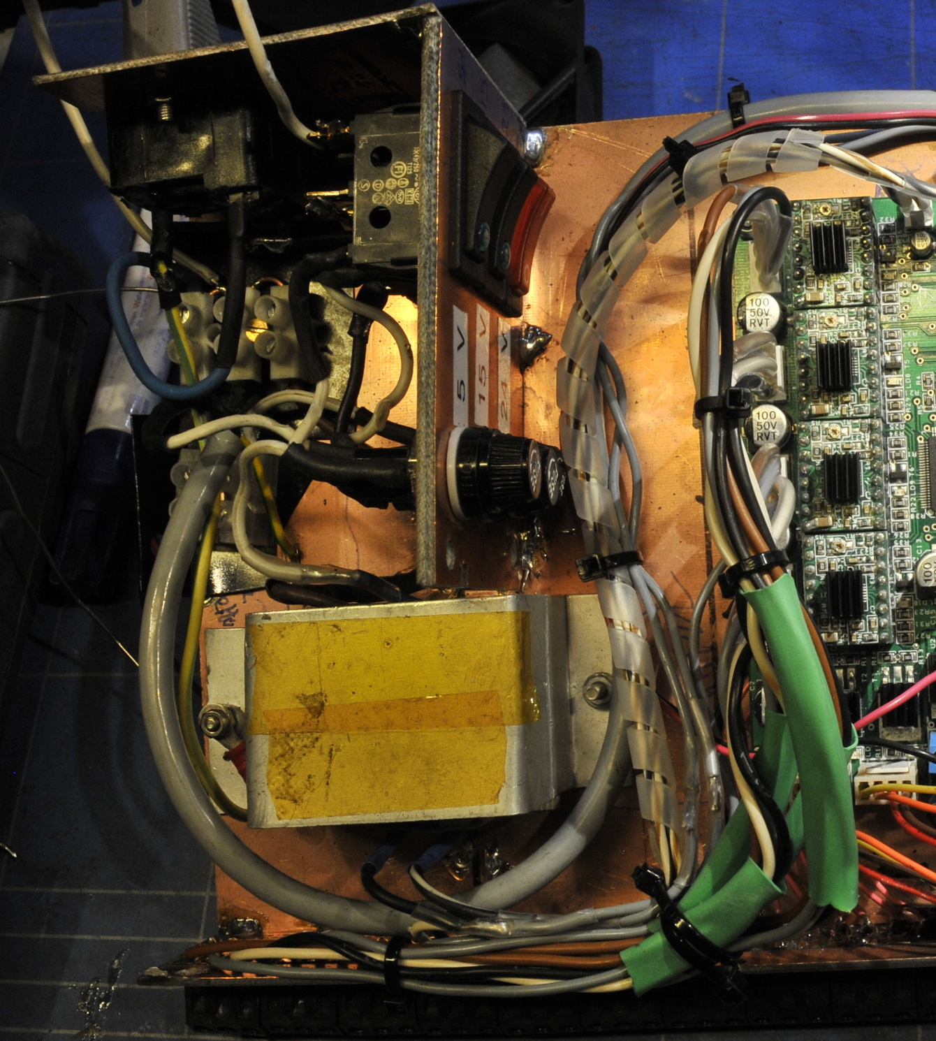
The controller:
Removed the original wire and connectors to the motors. Now they are connected with a thicker wire and soldered to the board. On the side of the mainboard I mounted a whole bunch of screw terminals. The stepperdrivers and mosfets now have a heatsink.
The diode between the 15V input and the 5V regulator is removed. The 5V regulator now has it’s own transformer (mounted left with the yellow tape.
12V powersupply:
The original Velleman psu is mounted in the most right tincan on the right. The power parts are mounted to the blackheatsink most right. The next tincan holds a < 50 Hz low pass filter to clean the psu. After the filter the 15V goes to a 723 based 12V psu capable to carry more then enough amps. The motordrivers have no problems with 15V but the fans and led lighting is made for 12V. Besides that I wanted to seperate the powersupplys so the current surges are seperated from the digital parts. The original psu was just capable of delivering enough juice to the printer. Now it only needs to feed the motors, fans and leds. The motors draw 1A. Current setting is based on Vref / ( 8 x Rsense) Rsense is 0,05 ohm, Vref is the value you set with the trimpot. so 0,425 / 0,4 = 1A per motor.
The 15V psu:
As a reference in case someone has to replace burned parts:The original psu is not a bad one. The build quality is not the best but also not bad. Caps could be better. I replaced one that had a rather high DF. The heatsinks are a bit poor. Just a few pieces of aluminium. Only isolated by the yellow tape. Not optimal for conducting heat. The mosfets used are 20N60C3, 650V, Rds(on) 0,19 ohm), 208Wspp_i and Id 20,7A
The diodes RF2001T3D 350VAC, 20A, Vf 1,3V, Irev 10uA, Trr 25ns
Bridgerectifier D5S60, opto’s HPCL-817, pwm controller OB2269CP
Heaters:
The poor original 15V psu was also used for the extruder and heatbed. The extruder is 6,82 ohm, the heatbed is 4,63 ohm. So together they draw 2,19A + 3,24A = 5,43 A
The heating takes almost forever. The mosfets in the controller are capable to deliver enough power but I wanted to be sure (pcb layout of traces and cooling) so I made a seperate controller. The originals now see a 470 ohm resistor instead of the heaters followed by a 820 ohm resistor that feeds an opto coupler. The opto controls a mosfet that feeds the heater. The powersupply is a 24V/10A transformer based Delta (the dutch brand that makes high quality psu’s. Heating the extruder and bed takes less than a minute (5,18 + 3,51 A so 10A is a safe choise)
I added 3 powerswitches that switch the mains , one for the 24V psu, one for 5V and one for 12V. The printer draws around 370W max (two heaters on) and around 75W while printing while both heaters draw no current.