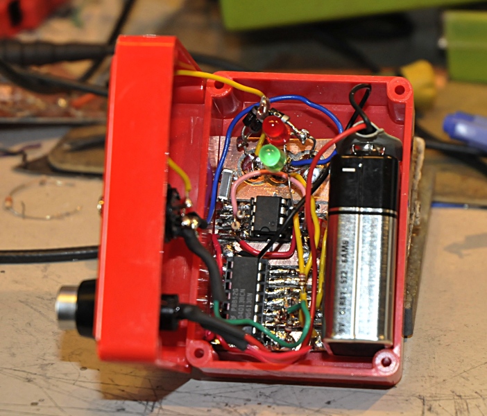
I made this just for fun. I found an old article in electronics world and I could not imagine this would work. They used a 7474 and there was a reset button between +5 and ground. I do not know the function other then shorting the powersupply. Because it is so easy I builded it. And indeed it did not work. I rearanged the 7474 connections and it worked. I have enough transitor testers but a small battery powered thing could be handy. I changed over to a 4013 because it can run on a 9V battery. The connector is a DIN plug . I made a shielded connection to it. There are handy because you can push a transistor in the socket.
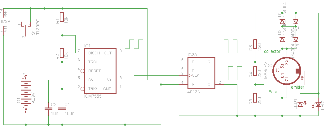
How it works is very easy. The 555 makes a squarewave of a few hundred Hz. I did not measure it. The original was 500 Hz . Tĥe signal goes into the 4014 and that outputs two squarewaves. If the Q is high, the /Q is low and vise vera.The base of the transistor under test (TUT) is biased between the two gates.
If Q is high and /Q is low the collector connected to the Q has a high voltage and the emitter connected to the /Q is low. If the TUT is a npn it will conduct. The voltage between the collecter and emitter will be very low. Parallel to the transistor and series diodes are two leds. Because it is parallel to the 0.1V and 1,3V from the two diode they will not light up. The next cycle the collector becomes low and the emitter sees high. The transistor will not conduct. The led that is forward biased will light up.
If it is a pnp it will work the same but then reversed. So if the emitter is high and the collector is low the TUT will conduct and the next cycle the other led will light up. So one collor for pnp and the other for npn.
If there is no transistors both leds light will blinck, because the frequency is to high for our brain it looks like both are lit. If you use a double led (red/yellow) it will glow orange./
If the transistor has an open CE the leds will both flicker because the Vce stays maximum. If the CE is short it will cause a low Vce in both phases and both LED stay dark.
It can be easy build on veroboard. If you want to be shure it can be always used in circuit you can make it work on 5V. Now the test voltage is around 5 to 6 Vtt.