
A lot of the measurement stuff I have, came to me in non working, or long not used condition. Repairing is something I enjoy very much. You learn a lot from it and if you succeed it feels good. A lot of people have troubles with it. Sometimes it is lack of knowledge but often it is also just a matter of not knowing where to start.
But this is not a tutorial for people who do not know a thing about electronics and just want to save money. Electronics can kill you and you can kill the electronics in a way no-one can finish the job anymore. If you know the basics and want to learn how to repair, or repair better this is for you.
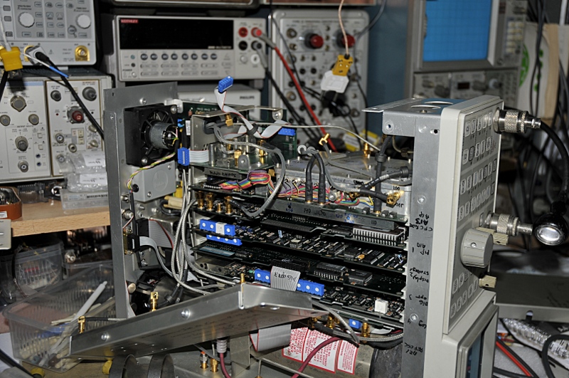
Sometimes it can be a lot of work to reach a component, like here in a SA to remove the YIG
You see a lot of posts on forums from people with a dead TV or audio amp who want to repair it them selves. The people who answer are most times pro’s and many failures in consumer electronics are known because they are sold in high numbers and often fail in high numbers. That makes it more easy. They often have a database with failures. But if your TV is not one that fails often, you can have a problem. Schematics, service manuals etc, are not always available and many products are just labels (not the manufacturer). So a TV from brand X and model Y can be made in several versions and from different manufactures but all have the same brandname and modelnumber. And most models are only produced a short time. Price is very important and that makes that they often build it as cheap as possible using many parts at the edge of failure. If it is made for a long time, it is often made in several versions that can differ a lot from each other. So get the right service manual. Sometimes you know, like a Fluke 77 without anything is the first version and it differs from a Fluke-III (mk-3). But for instance a Fluke 123 scopemeter made in 2000 is not the same as one made in 2005.
Test gear is an other thing as most consumer goods. They are often made to last, no expenses spared. (not the modern cheap Chinese stuff) And they last for long times but there comes a time even the best instrument will fail. For most this is true for the older stuff from brands like Tektronix, HP, GR etc. (they can be very old if they fail for the first time) There are very good service manuals available and instruments are often produced for many years. But if they fail, it is often more difficult because they can be very complex and build with special unobtanium parts.
Sometimes they are repaired before or modified. If you buy a dead one to repair it, be extra careful. If somebody before you failed to repair it, he can have made things much worse.
Most important is excluding things , logical thinking, knowing component behaviour, reading and understanding schematics. You learn a lot from repairing but start easy. Be sure you have the needed tools, the service manual states for a job. (or have the right replacements)

Often thing need to be cleaned first
There are two ways people repair stuff. The first is shotgun repair. You look up the problems on internet for the thing you want to repair and then replace everything you read about that could possible have failed. Often this is not the right way. You can be lucky or you can make things a lot worse. Some people start to do strange things like bridging “unknown” (by them) components and by this killing it even more. In consumer stuff caps are definitely number one in fail rate. So replacing caps often solves the problem. I repair some of my own consumer stuff now and then and , I too, do this some times. The power-supply from the leds above my aquarium died. Output had a large AC component. I opened it, 3 caps stared at me, one from a popped up open top. I did not waste much time. Replaced all three even without testing the old ones and it worked again. But that is because I know how that PSU works and what can fail. But what if this does not cure the problem ?
Then it is time to do it the right way. For most repairs I follow the same path.
First I will talk short about long not used gear. The problem is that the caps loose their oxide layer and start leaking DC, warming up and fail. If leakage is low there is a change the cap will reform and all comes well. But better save then sorry. I have a page on how to reform caps. If you do not want to take that trouble, starting it up with a variac and light-bulb in series is a way that can and often will work. But check also the contacts between boards, tube sockets, transistor sockets, switches, potentiometers etc. They often need some TLC.
Often failed parts are just a symptom but not the cause !!
First study the schematics so you get a feeling about what the function of boards and components are. Open up the instrument. Then do a good visual inspection and clean it out if dirty.
Fuses: check them, you won’t be the first to find out after hours of trouble shooting the fuse is missing or dead. If the fuse failed be careful. They can fail just for the fun of failing but often because there is a problem. If glass ones fail and they are sooted/black on the inside of the glass there is most times really something wrong. If they fail by them selves you can see the wire is open but no soot or metal droplets. Ceramic fuses must be replaced by ceramic. They contain sand and so prohibit the forming of plasma. Plasma conducts so the fuse blows but current keeps flowing. Replace a fast one with a fast one (F on the cap) and a slow-blow with a slow one (marked T on the cap) Also check the mains entrance There can be a fuse. A 100W light-bulb in series can protect the power-supply of the instrument you are repairing. If there is a short the light-bulb will light up bright and save the PSU you are repairing.
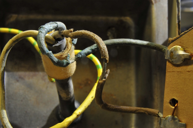
A good reason to always check the mains connection.
Potentiometers: K61 (a contact lubricant from Kontakt Chemie, but there are more brands with good stuff. But be careful, use the right stuff for the right job. The wrong type of stuff can do a lot damage. For instance K60 is good stuff but an aggressive cleaner for contacts. You can not leave it on the contacts, need to remove it (read the datasheets) If they are real bad, most potentiometers can be opened, cleaned ultrasonic and put together again. If the carbon film layer is worn you often can bend the wiper a bit outside the worn track but it is better replace it.
Switchdecks: ammonia or IPA (very pure alcohol) to clean dirt/oxide for silver. Ammonia removes the oxide but do not leave it on the switchdecks after cleaning. The black oxide on silver does not look nice but it is harmless. K60 and then IPA for copper contacts. For Gold only use IPA to clean dirt . Then dry it and apply some K61 or other good stuff. Do not spray the whole thing, spray some in a little cup and use a small brush to apply it. Some switches need petrol jelly, others need nothing. K61 is also good to solve problems with latching pushbuttons (almost every old long not used one will give problems) like Philips and Tektronix used a lot.
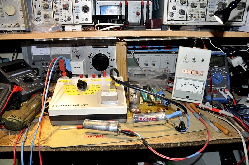
Capacitors: desolder one lead to measure and if needed reform them, see my page about reforming. After reforming measure DC leakage, capacitance and DF (or ESR). For most caps you can find datasheets if you want to know the values they should have. If they are good, leave them. Old Spraques in Teks from the 60’s are for instance often after 50 years still better as many modern caps. Check film caps that are on critical positions for leakage. ESR measurements in situ (on the PCB) are a quick way to test in a coarse way , but it is for sure not a good way. See my pages about ESR. If they measure low in situ they can still be high.
Tubes: If you want to take no risk, then make a socket that only has the heaters connected and plug a valve in it and leave it there a few hours to “de-gas”. I do not know if this is really necessary and I only do it to be sure in case when some very rare tubes are used. I use my tubetester for this.
Transistors: if they are in sockets pull them out and reinsert them a few times. If the leads have much oxidation I clean them. For instance with some steelwool or a fiberpencil or K61 etc. Be careful with germanium. They can suffer from whiskers or just leak to much. Test them in a curvetracer or transistor tester if you like but if they are bad you will find it later. One very strange failure is a transistor that does well using the diodetest or in a transistor checker but somehow not in the circuit. If you put them in a curvetracer you see a first trace *(see picture below from testing a good transistor), and that is what a checker does, just one base current, so one trace) but if the CT increases its basecurrent for the next trace, and nothing happens, all traces give the same response almost at the same amplitude so it looks there is only one trace, then hFE is good but hfe is gone. I do not know what is causing this but I have seen a few silicium transistors fail this way. If germaniums shorts through whiskers you can try as a last resort to heat the metal (melt the whisker) can with your solder-iron. If you are lucky the whiskers melt and the transistor survives. This will often not last but that way you can go on trouble shooting and replace it later.
Connectors and sockets: the same as switch decks. Be careful with gold, only use IPA, do not “sand” it.
Diodes and zeners, use the diode check on your DMM and hope the best. For a a zener you can use a powersupply and a resistor to limit current to a few mA . Then measure the voltdrop. Diodes do not fail often on there own. And if they do they are most times not the cause but the result of a bigger failure down the line. TVS is a sort of protection diode that goes permanent short and used the right way the fuse will blow and so protects the power supply. They go short is the voltage over it is to high.
Adjustable components. Mark there position with a fineliner. So if you have to adjust them, you know how they were set if you want to reverse a step. Often they are a way to test a function, For instance if it is on the base of a transistor adjusting the trimpot must change the current through the transistor so adjusting it must give a change in collector or emitter Voltage. If nothing happens that transistor can be dead.
Solder connections. I often use a microscope or magnifier to inspect the pcb on bad solderjoints. Often they have an other colour as the rest. Old gear from the 60-70’s then gets a dull solder surface. If you pick it with a sharp pin it sometimes crumbles. With a magnifier or microscope you see a crack in the solder around the pin. It helps to use a bright light behind the PCB. You sometimes see the light peeping through that crack.
After this I connect the patient to a AC lab-suplly but you can also use an isolation transformer (combined with variac and series lightbulb). Using the lightbulb; some gear I just switch on, others I use the lightbulb and / or variac. It depends on the type of powersupply. Some do not start if the voltage is to low.
The next step depends on what happens. If it shows signs of live but no smoke escapes and nothing gets to hot I start some operation tests to look what is not working. This can give you some clues. I use a (paper) notebook to write down things, like measured values, replaced caps, strange behaviour or failed tests. I use a thermocouple connected to a multimeter to monitor temperatures, an infra red camera or a Fluke contactless thermometer to quick scan for hotspots so I can switch off before the magic smoke escapes.
Fluke thermometer
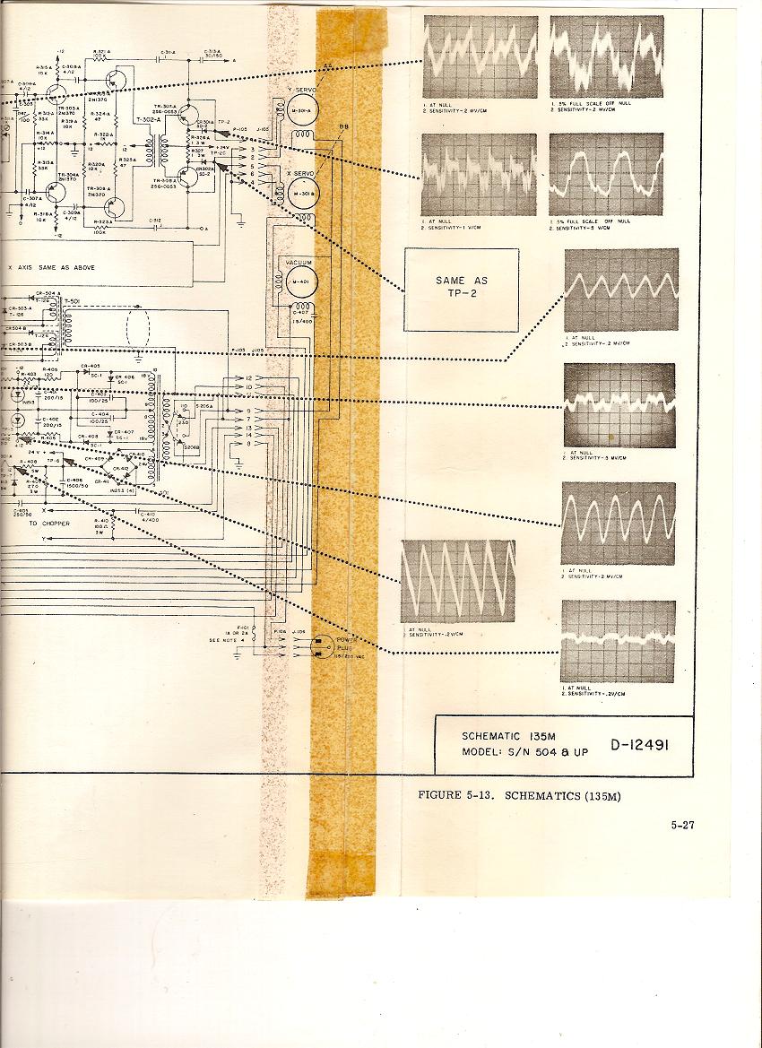
Now the real repair and fault finding starts. First I look in the schematics to see what group of components could belong to the failing function. Like for instance a to short trace in a scope could be caused by the X amp and related circuits. I make notes from that. Print the schematics and calculate and note voltages, currents (measured by the voltdrop over components) and waveforms on strategical points.) A bit like the manufacturer did in the picture below
But the most important thing is ALWAYS, no exception, first test the powersupply on ALL Voltages and ripple current/voltage. Als long as these are not spot on and according the manual you can not, and must not go on. I can not say this enough. Thus:
– measure DC Voltage with a good meter (with a fresh battery, or play it save and use a benchmeter). If you do not trust the result check you meter or test it with an other meter first. In old gear from the 60’s or older be careful, they often state a voltage for a certain meter. That will be an passive analog meter or a Vacuum Tube Volt Meter. I have written about that at the end of this page.
– measure AC signals if needed (for instance transformer output or heater voltage) and ripple on DC. This can be measured with an AC meter suited for the frequency with the right crestfactor but better use your electronic eyes, being your oscilloscope, that is next to your multimeter the most important instrument. For repairing a scope you DO need a scope and often a better grade as the one you are fixing. Many cheap meters have not enough common mode rejection ratio, a to low bandwidth to measure other things as 50 or 100 Hz sinewaves. The BW is only legal for sinewaves. The crestfactor tells you it can be used for non-sinewaves too. A good Crest factor is 9 or above, 3 is the minimum.
-check the voltage regulation by turning the variac something like 10V up and down. The service manuals often tell the range it must be able to regulate the voltage rails.
-Check current drawn by the instrument if you have the gear, this often tells you there is something wrong.
Be very careful using a scope in mains connected stuff. The ground of your probe is connected to the chassis. The chassis must be grounded so if you clip the groundclip to a live connection you short the line against ground and you can kill your scope, yourself or a fuse. An isolation transformer protects you against that, but it does not make it totally save for you, 230VAC from a beefy isolation transformer can still kill you if you grab the 230V phase and neutral at the same time.
Now we know the powersupply is OK we go to the next step. This I can not tell because that can be anything. But I will tell you some “tricks”
You always measure against a reference point. Most times that is ground or gnd, or one of the many names. Often connected to the chassis but not always. Some instruments have more then one reference. For instance the Tek 2710 has a SMPS with its own ground, called special ground in the manual. The normal ground is 50V above that. In a fluke 8500 there is a “ground” that is lifted 30V. I worked on an industrial tester that used 5 reference levels. But also in switch mode power supply’s you have to be careful for that. Most times the circuits are galvanic separated by opto couplers or transformators So if you use the wrong ground, your measurements are strange and wrong or you kill something. I often look for a known resistor or other component in the schematic that is connected to the ground of the schematic part I’m testing. For instance the gnd pin of an IC. I then use my Ohm meter (in the switched off instrument) to find a good point for my groundclip or multimeter probe. If that is the chassis, you will measure almost zero Ohm so you know you can use that. No handy place for your gnd clip ? Just solder a piece of wire to the gnd. The gnd clip-wire must be as short as possible. For DC less important as for RF.
Switch off the instrument, connect a probe and then switch it on, is the safest way. For you and for the instrument. Be careful around capacitors in SMPS that are connected to the mains. They will try to kill you. Also for heat sinks, besides hot, they can sometimes have a high voltage on them.
Some people think measuring current is hard and you need expensive broadband current probes for this. Indeed they can make live easy, I use them often. Current that flows through a resistor causes a voltage difference over that resistor. We call that a voltdrop. So If you know the value of a resistor, measure the voltage over it and divide that by the resistance and you know the current. Just Ohms law.
In case of a mixed signal (AC + DC) or pure AC but with a higher frequency and/or non sinewaves you use your scope. If you do not have differential probes you can do it as follows. Measure above the resistor. Note the waveform (from Vmin to Vmax and DC offset), then measure at the other side of the resistor. Note the values too. Now subtract those values from each other and you can calculate the RMS voltage and thus the current (see my page about measuring AC for the math) http://www.pa4tim.nl/?p=1023
http://www.pa4tim.nl/?p=481 These pages can be in Dutch, I’m translating everything but that will take a while. You can use two probes as a poor mans diff probe, but this is not as easy as it sounds. The magic word is CMRR but that is a rather complex subject on its own. I work a lot with diff probes. They make you can use your DSO scope as a scopemeter. DSO’s auto-measure functions are very good RMS meters. Often it is more then enough to know there is 5.25 V on a test point but the benefit of seeing things like ripple is big.
Transistors are easy to check in a circuit. For a npn transistor you have three legs and three voltages. The Emitter must show the lowest voltage (most times), the collector has the highest voltage and the base is somewhere in between. But the base voltage will measure 0.65V above the emitter (that is an average value, this can be 0.3 to 1V depending the type of transistor, current, temperature, but most are 0.6-0.7V). If you vary the base voltage, hence, base current, the collector and/or emitter voltage must change. If it does not the transistor can be dead. If you do not know if it conducts you measure the voltdrop over the collector, base and emitter resistors if used. If the current through the base resistor is 1 mA, but the voltdrop over the collector resistor is zero volt there is something wrong. PNP is the same but the emitter is 0.6V above the base, the emitter voltage is here the most high one.
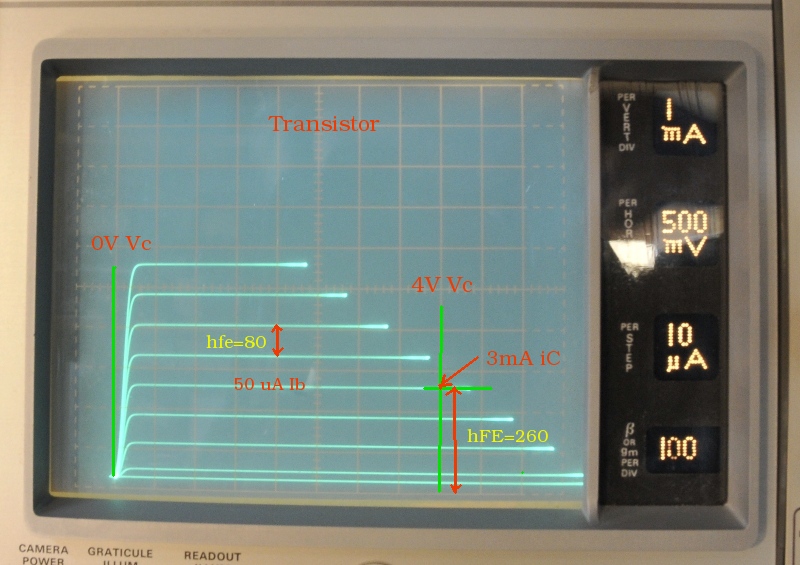
Hfe and HFE of a transistor
Opamps are easy too. Look up the datasheet for the pins. Check the Voltage on the powersupply pins. Often a positive and negative rail. If they use it single rail there can be a reference voltage somewhere in between. The differential voltage between the inputs must be the close to zero. But the voltage on each of the inputs alone does not have to be zero, they must be equal so the difference is zero. Look up the formulas for gain in an opamp book and together with the voltages on in and outputs and the voltdrop over in/out, and feedback resistors you can calculate if the opamp still works. And if it is amplifying an AC signal you can measure the gain between in and output. You can desolder it, push it on a breadboard and test it by building a simple amp.
Instruments with inputs. Like a scope, multimeter (or audioamp, radio, tv). Here you can feed the input with a test signal. Connect the source (often a function generator, but sometimes you can use a soundcard, mp3 player, voltage source etc) and follow the signal according the schematic. If you lose it after a transistor or opamp or tube, you know there is something wrong. Then check that component and connected components by measuring voltages as stated above. Be careful, some components act as converters. So if you lose a signal it will not say that there is a problem. It can be converted in a current, or a frequency. So check that. Also make sure you terminate generators or inputs and outputs from the patient when needed with the right impedance. You often need adapters, attenuators and other couplers for RF. This is GR stuff but it is just an example.
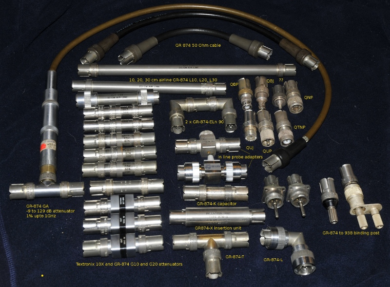
Part of my GR -874 collection
An external PSU. Sometimes a part of the circuit pulls down a psu rail. So the rail itself is OK but the circuit behind it is wrong. Testing it that way can damage the supply or circuit. It is sometimes possible to disconnect and isolate that rail and connect a lab supply with adjustable current limiting. So you can limit the current, protect components from becoming to hot but still be able to do some measurements. And it is often also possible to place a load on the powersupply you are repairing. Most power supplies need a load to work well and this protects the rest of the instrument you are repairing. A modern intelligent battery charger often works only if a battery is connected
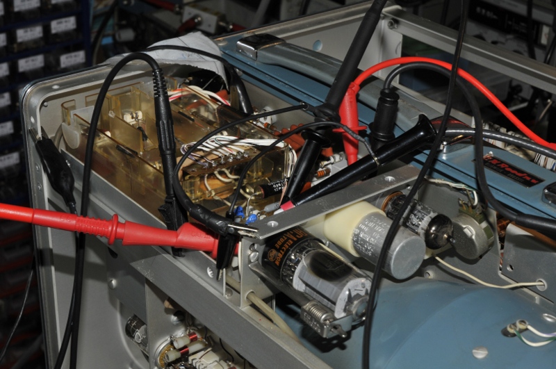
Close up van probes
Probing: your scope probe has capacitance and resistance. So it loads the circuit you are testing. An oscillator can stop or an amplifier can start to oscillate just because you probe it. The capacitance is often between 10-40 pF, At DC that is a huge impedance but at 100 MHz that can make that your circuit sees a 30 Ohm load instead of > 1MOhm. Naturally you first used the scope calibrator to compensate the probe. If you measure above a few kHz you best use 10X probes. Remember the 3dB point of a scope is 0.7x the measured amplitude. So a 100 MHz scope will show 1V as 0.7V at 100 MHz. But that does not mean it shows 1V at 90 MHz. Somewhere between DC and 100 MHz the Voltage will drop. A 100 MHz scope needs a probe that is made for a 100 MHz scope, that is not the same as a 100 MHz probe. If the probe itself is 100 MHz too, it will attenuate the signal at 100 MHz with 3dB, so did the scope so you loose 6dB !!
The groundclip of the probe is an antenna. Clip it to the point of the probe and you can use it as an antenna to look for RF radiation. For instance look if an oscillator is running without loading it. But that lead clipped to the ground will also receive signals and pollute your trace. So interference on a trace is not always coming from the circuit testpoint. At higher frequencies you best use a ground spring on the bare ring just above the probe tip. And if the probe loads the circuit to much use a 1k or 10k resistor between probetip and circuit. This lowers the capacitance of the probe.
Groundspring
Multimeter test leads form a nice dipole and can pick up garbage. Use in that case shielded leads ot twist them together. This reduces the selfinductance and noise pick up (that selfinductance can be around 1uH and cause ringing and overshoot in fast circuits or even oscillations).
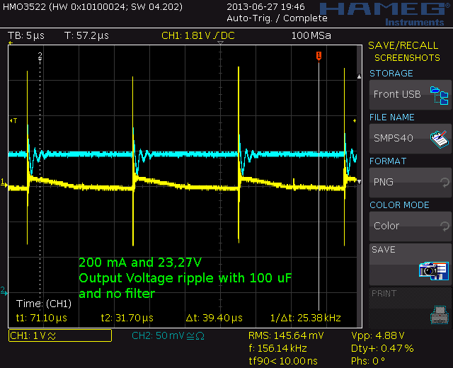
200 mA, Output voltage ripple. 100 uF, no filter, dirty probing
About oscillations, if you measure , using a multimeter, fluctuating DC values that make no sense behind for instance an opamp or voltage regulator there is a good chance it is oscillating (or there is AC). A scope will tell you what happens.
The input resistance of a multimeter is also something to take in account in some cases. If that is 1 MOhm and you measure the voltage on a point that has a 1 MOhm resistor to ground your meter will show half the voltage (for instance a grid leak resistor, or the voltage divider resistors of a scope HV CRT feedback) So in those cases look up the Rin of the meter and calculate the results. The source in that case sees 1M parallel to 1 M and that is 500 kOhm, so not only voltage will be half, in most cases the source must deliver twice the current. Not all sources like that and drop their voltage..
For this an extra warning if you restore pre-70’s stuff. The values given in schematics are often given made with a certain type multimeter. For instance an old broadcast radio from the 30’s will give a voltage measured with an analog meter. This can be a low impedance passive meter or a high impedance tube voltmeter. A passive analog meter has an impedance given in resistance/Volt. If this is 20k/V this means that the 10V scale is 10x20k or 200 kOhm input resistance. So measuring the voltage over a 100 k resistor with a modern DMM gives a higher value as measured with that old meter, so if the manufacturer used a 20k/V meter you must correct the given values for your meter. Most modern meters are 10 MOhm or even more. Cheap “toy meters” are often 1 on or 2M. A tube voltmeter is often comparable to a DMM. HP and Tek manuals always have a list of the needed equipment.
A tool that is handy sometimes is a simulation program like spice. You can simulate a small part of a circuit and change things until the simulation shows the same behavior. For instance short a transistor in the simulation and look what happens. Or to learn about the voltage of waveshape you can expect.
An other form of repairing are boards that belong to a bigger “something”, for instance a servo controller from a big machine. In that case you often can not power the board because you miss signals from f.i. sensors. You can sometimes emulate things by connecting voltages, resistors, switches, digital signals etc but that is not easy. Most times it is not even possible. The manufacturer often has special test systems for that. In those cases you can desolder parts partly or totally and test them in some special component tester (LCR meter, transistor tester, curve tracer, SMU logic IC tester, triac tester, optotester, relaistester, 78XX tester etc etc. I have a lot of instruments for that, both commercial build or DIY, that can test parts. And then there is the old breadboard. Take the datasheet from an IC, it often even shows the test methodes, and build a simple circuit to test it on a breadboard. For SMD it is also doable if you buy some adapters so you can puch it in a breadboard. To measure or test small SMD parts like f.i. resistors or SOT23 etc, you can use a piece of double sticking tape. Tape it to a piece of PCB stock or cardboard and you use the sticky top to hold down the part you want to measure.
Desoldering
You must be able to desolder stuff. You need a good (de)solder station (I use a Pace SX100) for that, or you will damage a lot of solderpads and even worse vias. For SMD I use hot air. If you lift a pad + via in a multilayer board that has inner layers, you have a huge problem if the via was connected to an inner layer. You sometimes can repair that but this is most times far from easy and you need special stuff like 2 component glue that does not melt while soldering the new glued in trace, you need vias in all sizes and tools to place them. Most failed repairs are caused by unsuited (Cheap Chinese) (de)solder gear
For incidental repairs you can use wick to desolder.There are many tricks to desolder parts shown on you tube. Some are good, some not so good. Some are good but need a lot of practice but look easy.