While repairing it is very convinient to see the voltage and current from the instrument or other equipment you are working on. I used a P6042 current probe but that is not always easy. You need to find a single mains wire to clip the probe on. Most times I use a variac and isolation transformer between mains and DUT. It has an analog Voltage meter but not one for current.
When I was visiting my good friend Rene, he came up with this idea. He designed the core front end. He has a lot of professional experience in this field so that was a good start. Safety first. I followed most of that because we use the same opto couplers and that was rather tricky because we wanted a 1 MHz bandwidth and AC + DC TRMS.
Just for fun Idecided to build my own TRMS converter. That turned out not as hard as I would have expected. The schemic is based on appnote, LB-25 from National semiconductor. (linear brief nr 25 june 1973)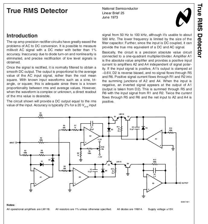
The biggest problem was measuring the AC Power. You now think, duhh, that is just U x I. Yes, that is, but only fore a sinewave. The voltage and current do reach their max at the same time. The phase of those two are equal in time. But if you use a pure reactive load like an inductor or a capacitor you get a phase difference between voltage and current.
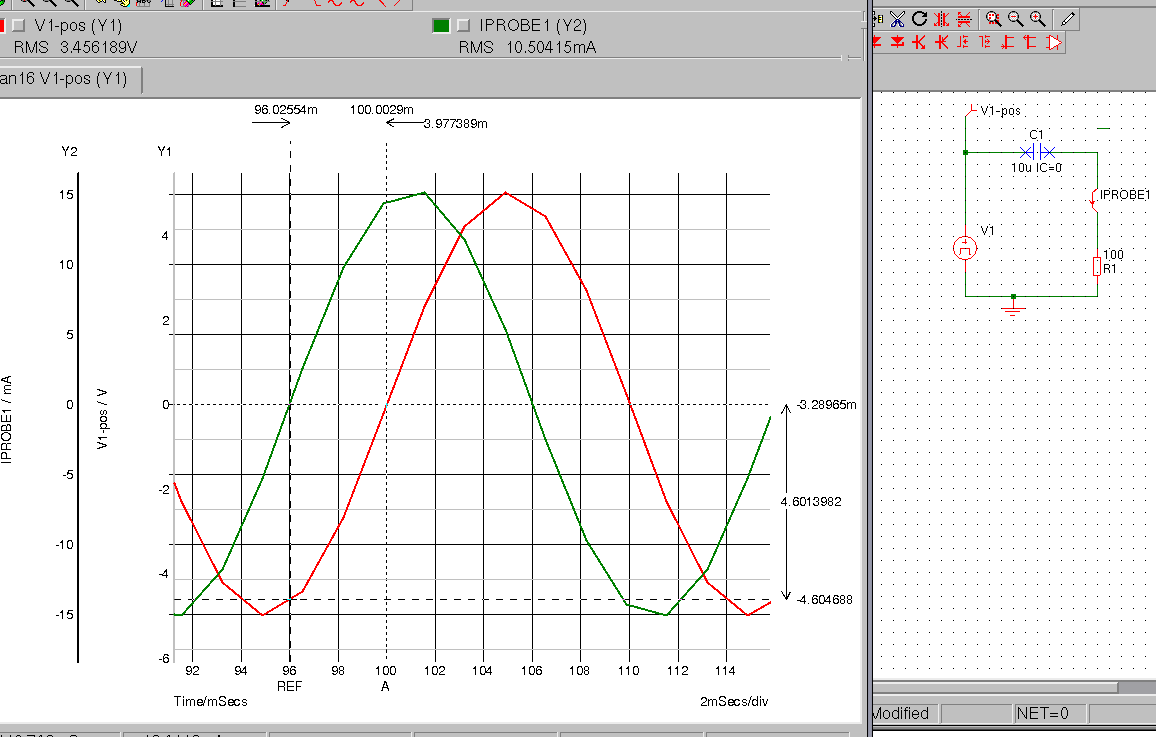
This is a capacitive load. The Red trace is the voltage, the current leads the voltage.
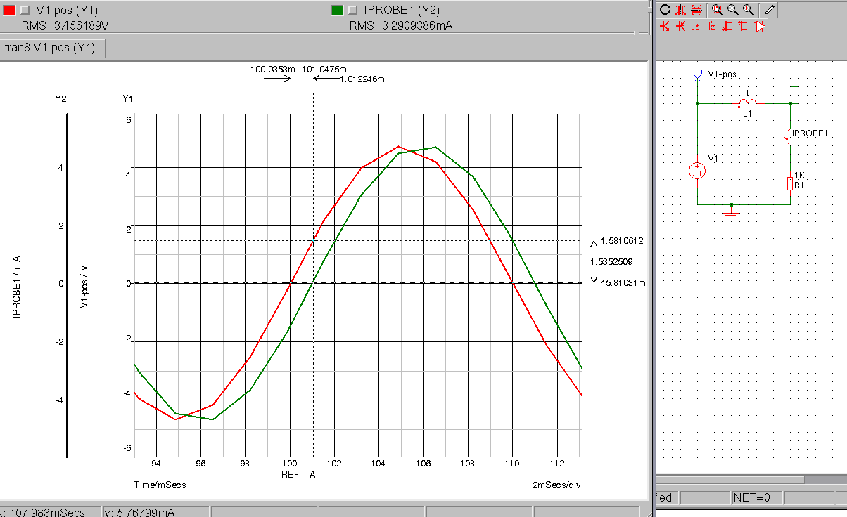
For an inductive load is it just opposite

And this is like we want it to be, when we use P=U x I.
As you know (if not, you know it know 🙂 ), a pure reactance (ideal inductance or capacitance) does not dissipate power. In that case there is a 90 degree difference between voltage and current. The load does not dissipate the power so it goes back to the source. Just like it does for RF to a not matched antenna. This reactive power is called Q. The square-root of Q squared and P squared together give S , the displacement power in VA (volt-ampere)
For electricity companies this displacement current S, is a problem. They must produce this current and transport it, but do not get paid for it. Big users in the industry must compensate for the displacement current they cause . Most times Q is inductive because of the big electromotors, so they must compensate this by placing capacitor banks. Like all imaginair vectors here capacitance can be canceled by inductance. So Q=10W, P = 100W gives a S of 100,498VA. and a power factor of 0,995. But if it was Q=10W and P = 10 W then S would be 14,142VA and a PF that is 0,707. So you use and pay for 10W but you need 14,142 W . You do not pay for the 4,142W (I hope ). PF will be 1 if all power you draw from the grid is used and zero if you feed a pure reactance, in that case, all current will be returned to the grid.
But so far no problem. Two sinewaves and a nice detectable phase shift. That is in theory, in the time everything was linear build. No look how a modern laptop psu draws current:
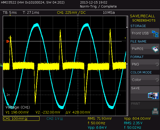
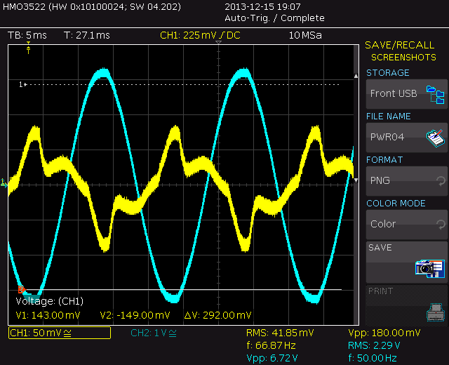
Here screenshots from the isolated bnc outputs of my meter, the laptop is powered but not performing jobs, just the sceensaver. This is not a bit like the schoolbook phase shift. Here the current (yellow and 3.4% duty cycle) is leading and lagging in the same cycle. The voltage goes up, the powersupply, running at a much higher frequency gets his energy from the caps.
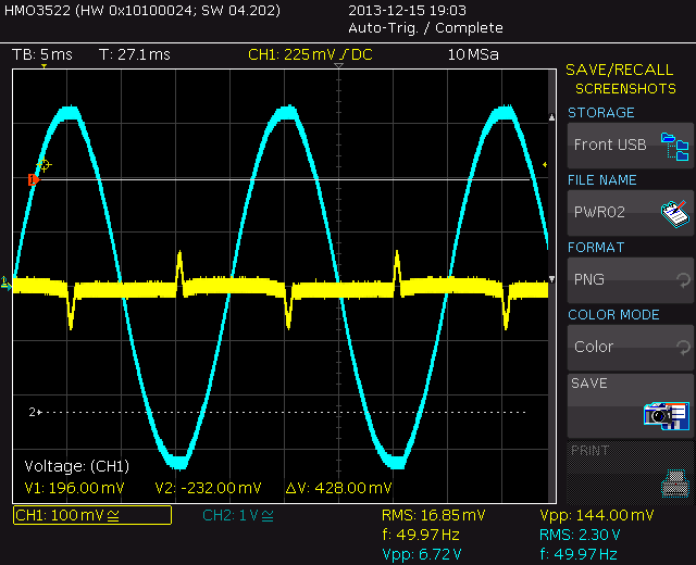
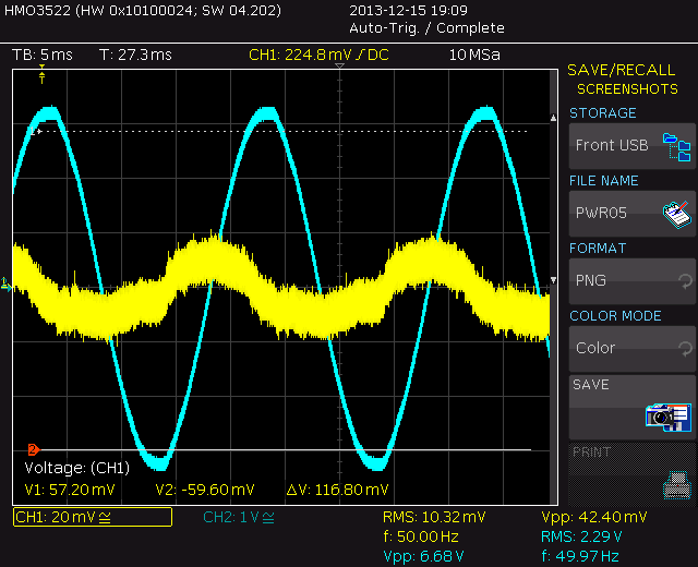
Here it is powered down and only charging
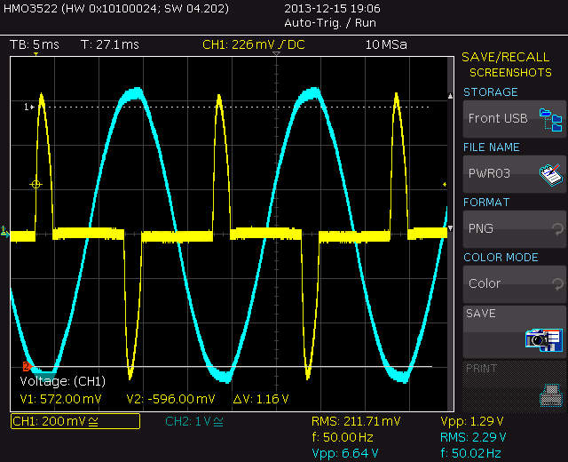
Here it is spinning the harddisk. The spikes are much higher and the current spikes are wider but it is not easy to talk about phase shift here.
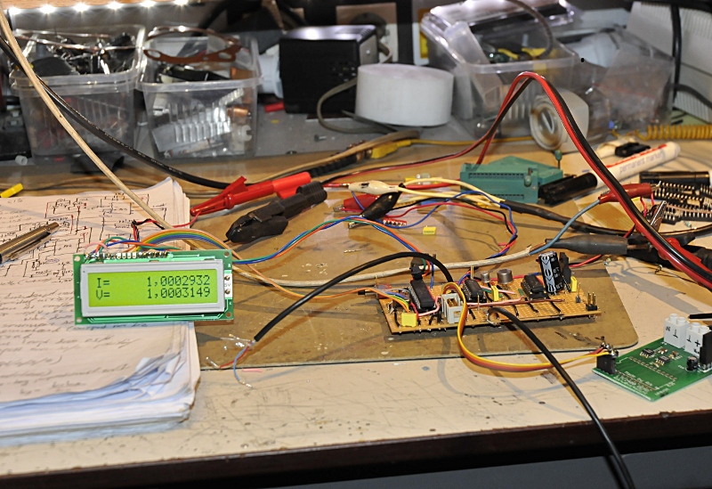
This is transformer feed 1960’s electronics. Here you see a phaseshift in the classic way. 200.006 mA, 232,768V and (46,55W -j 46,11W) makes S = 65,5VA at a 0.71PF
It has an oven inside and down here the oven is in standby mode, 0,0364A gives 8,471W+j57,8 = 58,41VA
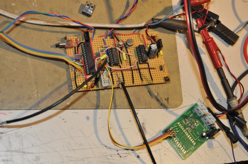
The meter is made in a few blocks. The front end measures the voltage and a second channel measures current over a shunt. After photo optos the second part scales the signals and measures the phase shift, that is, they measure phaseshift and the cpu measures the dutycycle.
The RMS adapter can handle a mixed AC and DC and works up to around 500 kHz. The opto part goes up to 1 MHz. But like all RMS converters it does not have an unlimited crest factor.
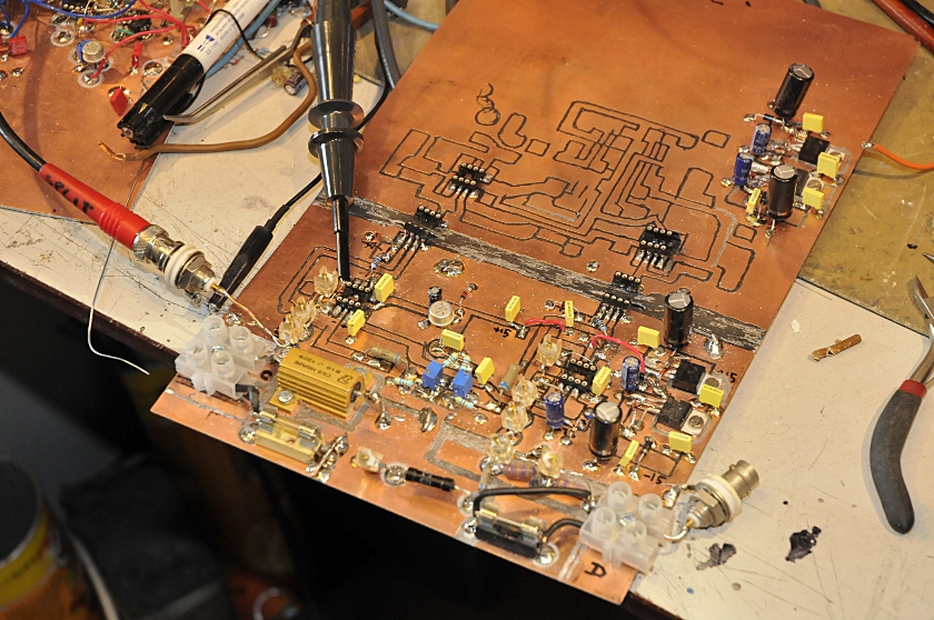
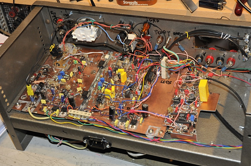
Building the high voltage part. In the middle the copper is remove and fiberglass is removed for isolation.. The pcb is milled by hand.
Because the isolation needed there are several galvanic isolated powersupplies.
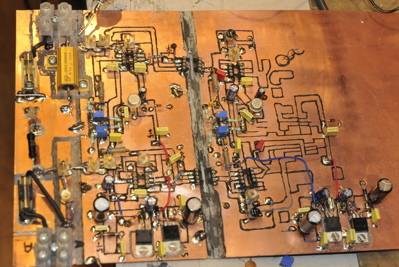
The microprocessor is an Atmel 328 programmed by an arduino. The ADC is a 24 bit LTC2400.
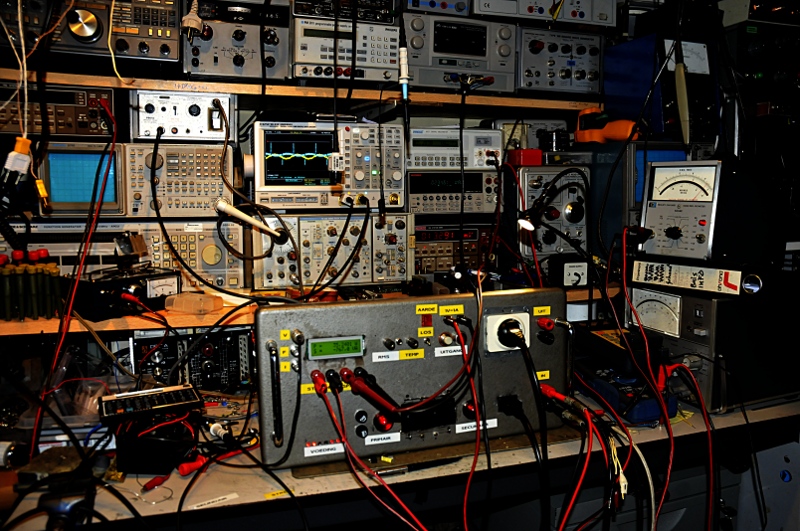
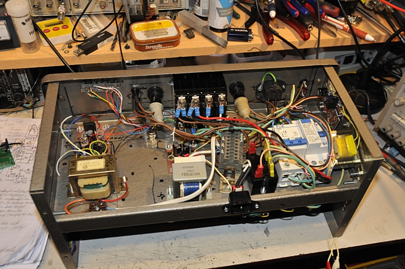
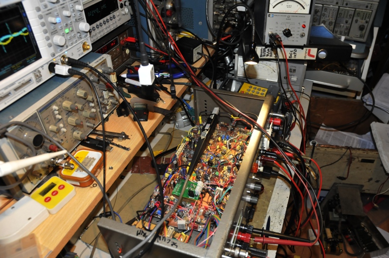
Mounting everything in a cabinet. I could make it a lot smaller but I wanted to use this cabinet because all transformers, relays, automatic fuses, earth leakage protection etc takes a lot of space like you see on the next picture.
It looks like it is made from Lego with all those colored capacitors.
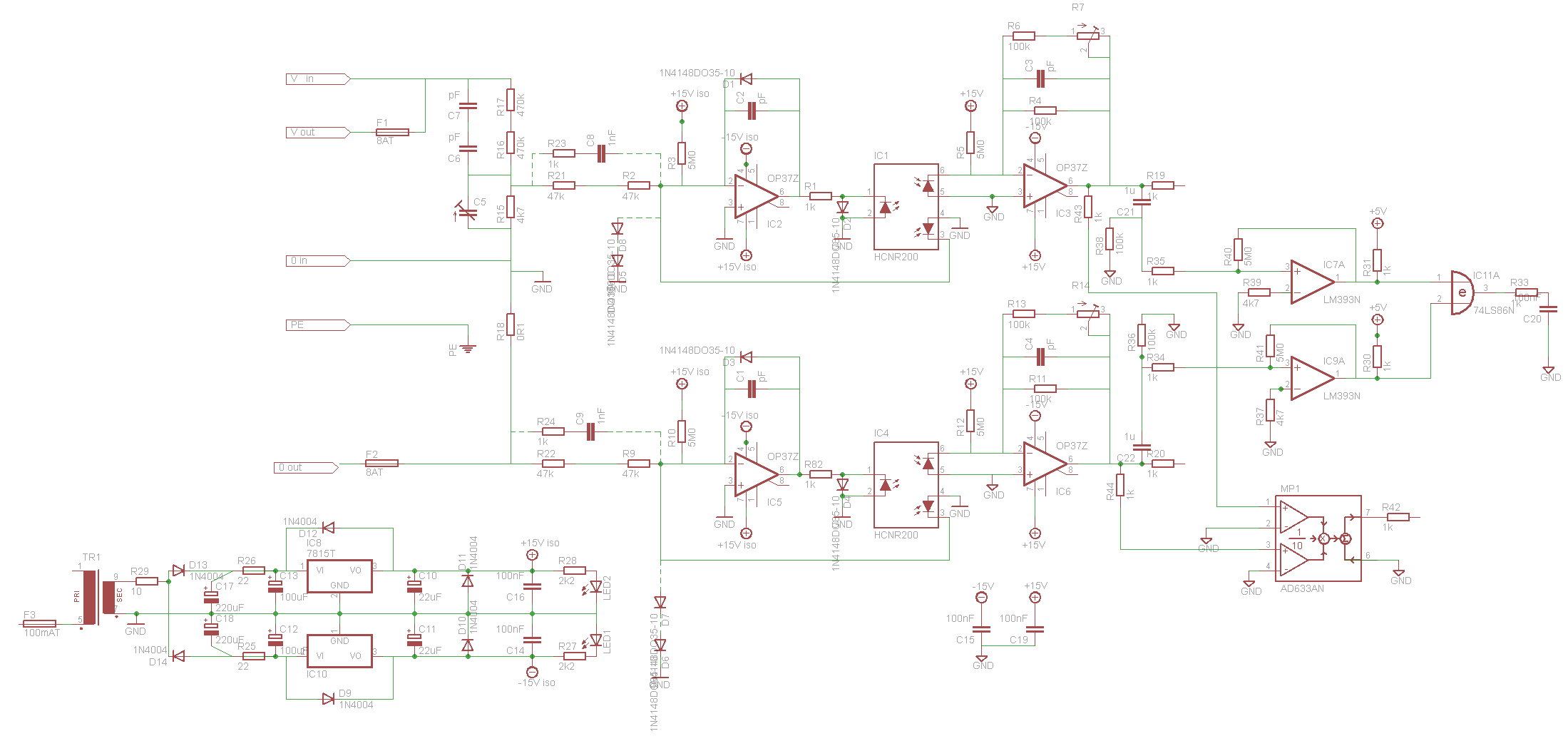
Schematic front end, I followed this for something like 90%. This is not an easy to build design if you want a lot of bandwidth. A lot of things are tweaked and changed during building and testing. I’m very bad in documenting that and because faults in the schematics can cause dangerous faults I have not documented everything, The front end down here is the most important part and is very usable as a base. Feed it to some digital stuff like an Arduino direct or through some external ADC and add things you like etc.