In the Bob Pease show, What’s all this Wattmeter stuf anyhow, Bob shows a powermeter for0-1500W (at 110V) , The transistors multiply the currect times the voltage by modulation. The Result is TRMS power. So if you connect a capacitor as load you only see the power dissipated in the ESR. It has no problem with inductive or capacitive loads like many cheap powermeters. He demonstrates that in the video.
The original from Bob Pease
This is a real Pease desing where he get a very good result with a few parts. In the video they use a Agilent benchmeter that shows DC but if you look good you see they masked the display with some tape. In his article he uses a 1 mOhm shunt. A huge spider made from wire. The power meter he shows has different ranges and he writes you can use an analog meter.
Ugly betty, a powerbabe.
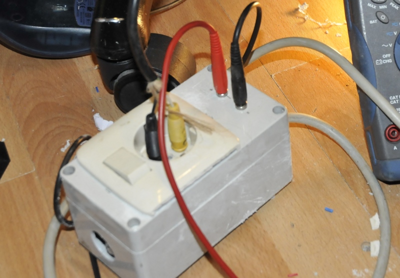
At first I only made it out of curiosity, but it turned out to work very well so I put it in an old box, mounted sockets and it turns out to be a very handy thing and a good example about how NOT to build something that carries 230V (the pcb down here was just to test it.)
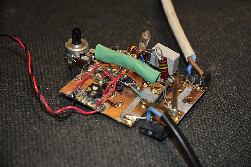
The pcb
In the green crimphose are two 100 kOhm resistors in serie. This is for safety. 230VAC is around 700Vpp and above the rating of most resistors. The shunt (the golden upsidedown ” V” is on a separate PCB. The neon light is a power indicator I removed when I put it in a cabinet. The red and black go to the multimeter. 1 mVDC is 1W.
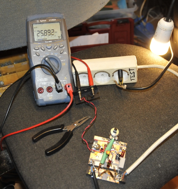
Demo for picture
The output is modulated ” DC” . I could not get it to work with an analog meter. If I added an opamp I managed use an analog meter but needed external power. Idem for the digital modules on the breadboard. I have plenty DMM’s so I use it like Bob. I made this to monitor instruments while repairing or reforming. The switch is to shut down power. I also placed a fuse. I adapted the schematic for 230V. Made a 10 mOhm shunt from a goldplated strip (so 1 mV is 1W) . Selfinductance is very low and I did not bother to optimise that because I only use it for 230V. It does not need an powersupply. The 100 nF , resistor, diodes and zener are the powersupply. I used a double transistor, some old Philips I had in the junkbox. But you can use two BC547 or other jelly bean transistors. But connect the housings for good thermal contact together.
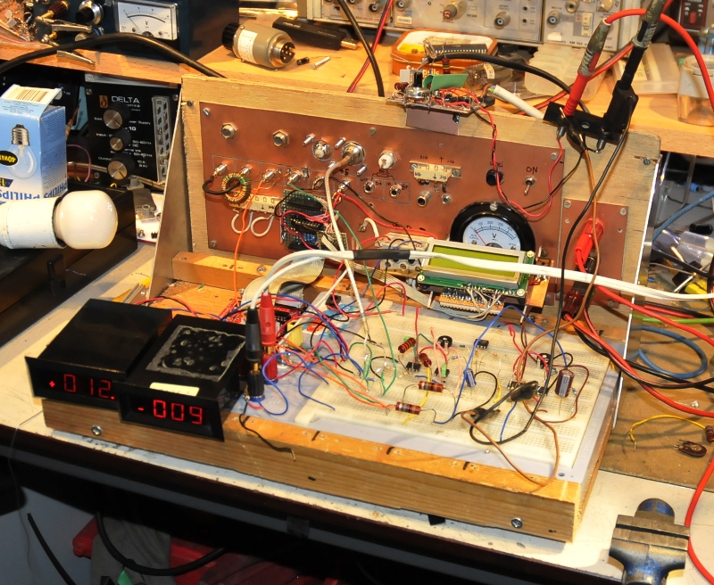
Some powermeter testing on my breadboard
Here it is mounted on top of the breadboard and I use opamps to monitor current and power. The current probe is the torroid hanging on the black wire left on the backplane. The opamps are not intended for this but are a test setup for an other meter I’m designing that will do power, current, voltage and powerfactor. Here I use them with the Pease meter only to look how the opamp circuit behaved and if I would do the trouble off adding that to the Pease meter so I did not need a seperate multimeter.
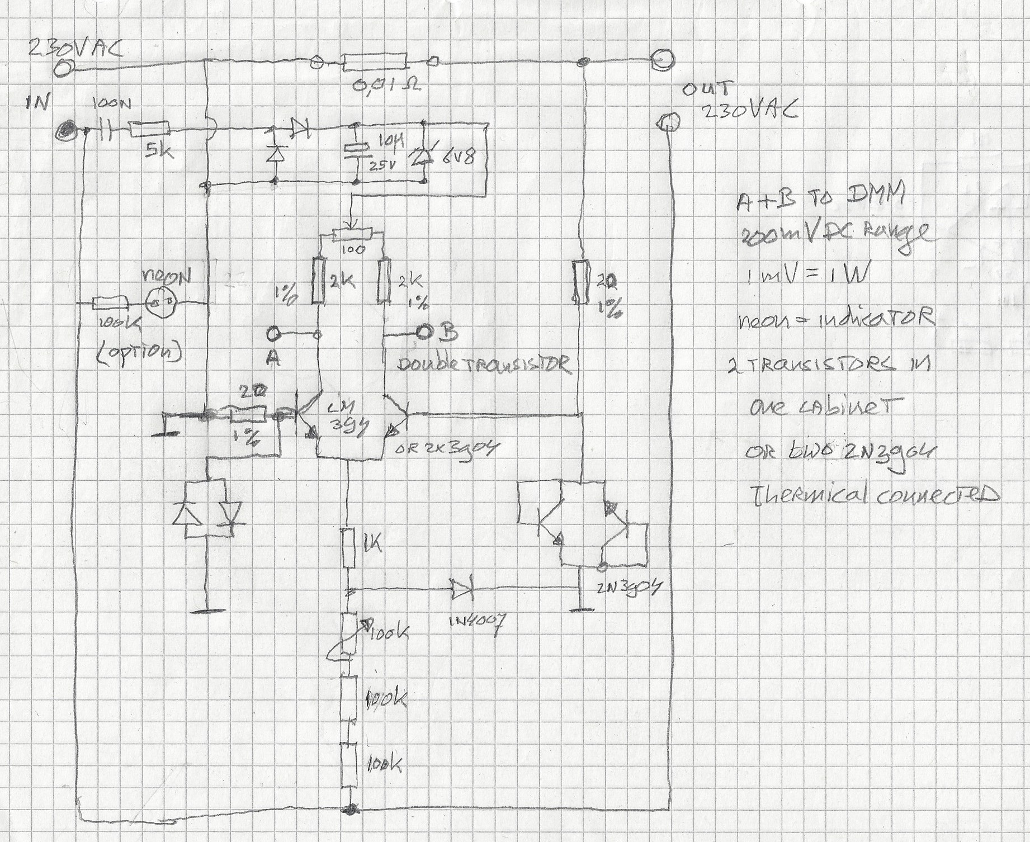
230V schematic in Fred-cad