GR-1603A ZY bridge
Thanks to my friend Ken for finding this beautifull bridge and sending it from the states to here. The nice pictures are made by Ken who even cleaned the unit before shipping.
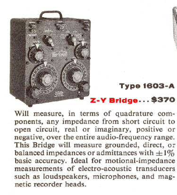
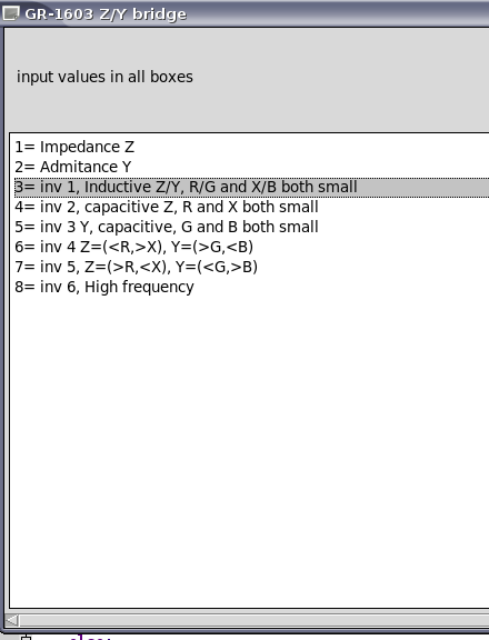
The GR-1603a was introduced in 1955. It is able to measure Z in rectangular format. So Rs an jX and Y in G and jB. According to GR it was capable of measuring every impedance or admitance. But it is not a brifge for the faint hearted. It has 8 modes in which you have to do things in the right order, note some in between results and do some math to get the result.
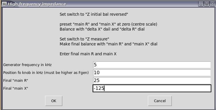
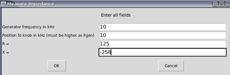
I wrote a program in Python to do the math for me. Here are some screenshots from the first tests. I have not checked all math yet but this is the code, just rename it to GR-1603_gui.py and run it as python GR-1603_gui.py or in Debian build it with Geany (you need the easyGUY lib ) and run it from the menu as terminal program and the command:
“python /home/your_name/your_dir/GR-1603_gui.pyc”
(edit 5-7-013 new software version. Tested almost all modes exept 6-Y-inductive because I could not find a right component yet
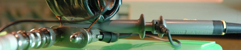
It needs a separate audio generator (20 Hz to 20 kHz, upto 150Vrms) and Detector. I have the original but for “mobile” use I will maybe make a small modern battery operated detector/oscillator unit. Down here you see the one that is on my GR1620 but I have a second one. Not as good as this one. It has a higher noiselevel so I must have some TLC. The problem is they need 12V made by 9 x M72 mercury Cells. They are very short “D” cell diameter cells and unobtanium. So I used an external 12V like my other detector. Today I made a battery replacement. It only draws a few mA (< 10 mA) so I took 4 CR lithium cells. Like you use in calculators. Put some shrinck tube around it and made a dummy pack. I soldered wires to them. Be carefull, better make contact strips. Lithium batterys do not like heat and can exoplode.
The hole that holds the 4 coin cells
I used a piece of airhose. That fits perfect. the metal ring is original and now is used to close the battery department. I made contacts from pcb and there is a core of foam in the hose that pushes out the pcb so it makes good contact. Nois level when zerod dropped from 40-20 on the scale.
The dummy battery pack
de detector GR 1620
It is AC coupled so you can measure DC biased components like batterys, powersupplys or DC behaviuor of electrolytic caps. It can also be used to measure the Zout of amplifiers or loudspeakers.
It is not the most accurate tool in the world but like GR told at the introduction, there is no other brifge that can do the same. It can measure everything from short to open. It it so so bad as some people think. If you use the different modes the right way it will supprise you. Mine needs a bit of recalibrating because if I zero the bridge and then measure open, short and load it is not 100% accurate. 50,17 Ohm reads as slight under 50, I guess around 49-50 Ohm (still better as many cheap multimeters) . For open you use Y, and that must be 0+j0. This reads G slight over 0 (about 0.05-0.1 umho I think) but that is > 10 MOhm and a bit of dirt will cause the same leakage. A short with a groundstrap under the terminals reads in Z 0+j0.1 (also a rough estimation because the scale is coarse. In mode 1 or 2 you can measure this more exact. And at 10 kHz this should be lower. If I set the dials right and zero it with the delta sials too and use this setting, the other measurenents are correct. So for more accuracy there are some tricks. Just calibrate it like you do a vna and the measure the DUT.
But even like it is, it is more then close enough to be usefull for many things.
Because it is audio and 600 Ohm was the standard back then it is most accurate in that area. A simple trick is measuring very small impedances in series with a 600 Ohm resistor and very high ones with a 600 Ohm parallel and then calculate the right value back. If B or X is very lare or small you can do the same with a 600 Ohm or umho reactance. But most times the modes from table 2 in the manual give you a usable way without tricks.
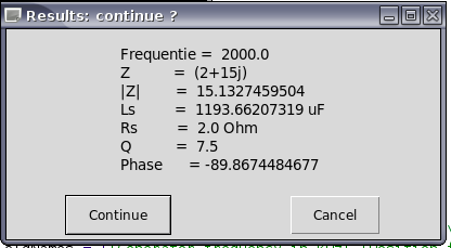
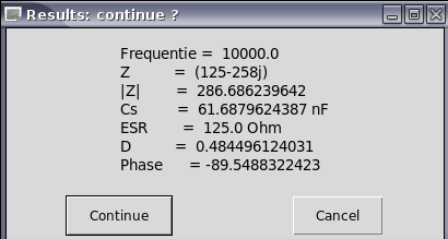
I did some tests at 10 kHz:
a capacitor, 2,488 uF with a 0,18 Ohm ESR at 10kHz, that is Z=0,18-j6.23Ohm. The bridge measured 0.1-j6.6 Ohm or 2,49 uF
a torroid, 24.58 uH and Rs 0,14 Ohm. But the bridge measured with 3Vrms, that is a lot more as the LCR meters or mij L bridge and cores react on current. It measures 0.1+j1.85 or 29,4 uH.
A 85,2 pF cap measured in Y mode 92,9 pF. that is 9% off but it can be better, It were just quick test. For instance if my generator was 100 Hz off the result will be different too. Best to measure this before serious measurements.
A 3,287 mH inductor with a Rs=28,7 Ohm measured Z=30+j209 and that is 3,326 mH so very close.
This is the impedance of a 600 Ohm headphones:
A 600 Ohm headphone from 20-20000Hz
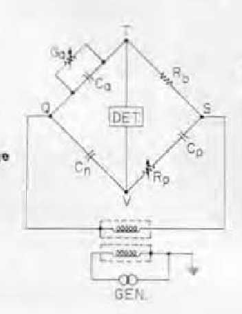
bridge layout
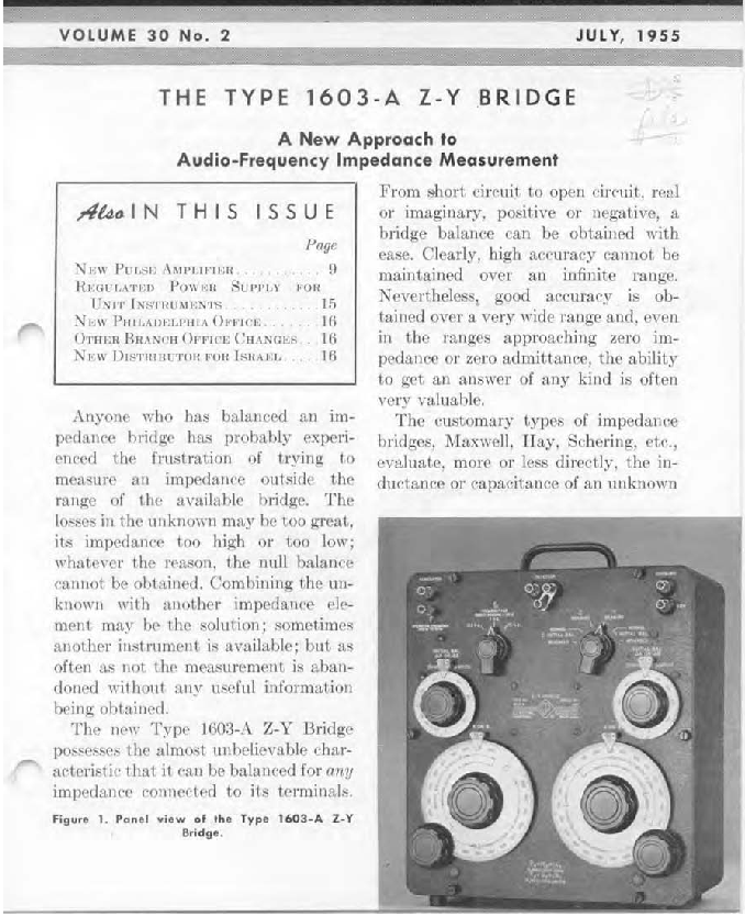
Introduction from GR experimenter july 1955
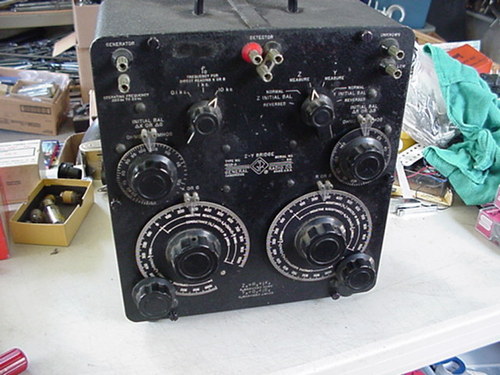
before cleaning
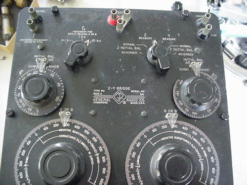
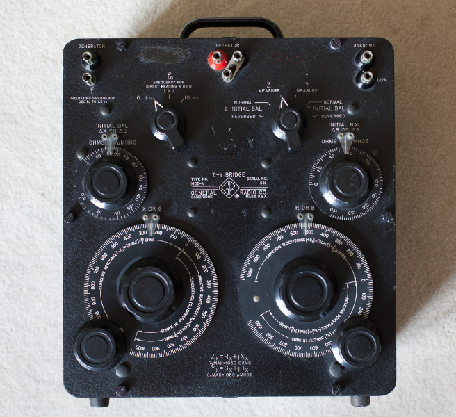
front details
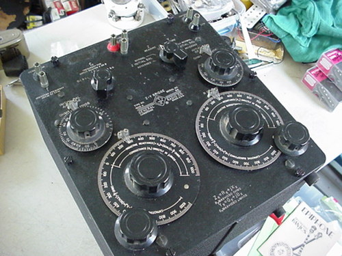
Front
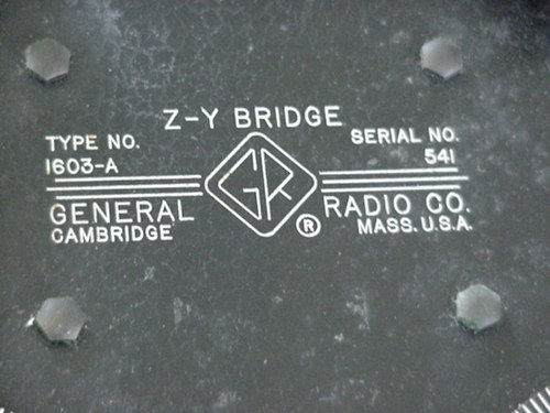
Type and serial number
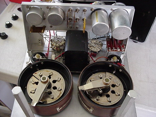
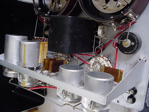
The two giant potetiometers
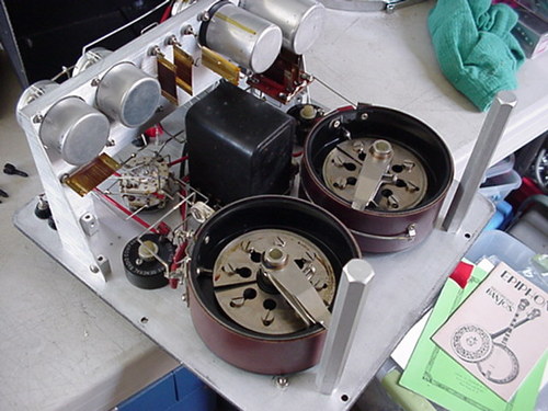
The inside from an other angle
The arm standards
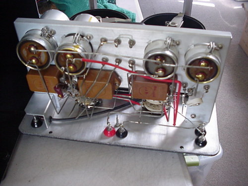
More details