Inductors are hard to measure components. Beside things like the usual parasitics (capacitance and resistance) they act as antennas, sometimes even corupting the measurement. If they pick up a strong radiosignal on a frequency they are resonant your meters can go bananas . Often you can suspect this if the readings of your meter are all over the scale. But that is not all, they are also very good in “loosing” signal to the surrounging area. Another thing to be aware of, is the huge influence the surrounding can have on the selfinductance. Things like lare metal objects nearby, but even the magnitude from the current of your L meter will influence the measurement. Not all those effects are as big and often depending on other factors too. And that makes it so difficult. There is no “good” way. There are mostly “not to bad” ways for “that” inductor in “that” place and at “that” frequency.
In a General Radio Experimenter from 1960 I read an interesting article about measuring inductors. I have some stable aircoils from some militairy gear, they are 3 and 7uH and some GR adjustable inductorswith higher values but I was curious if it would be easy to make a bigger one that is shielded and with low paracitics, not to much antenna behaviour and not to sensitive for surrounding influence.

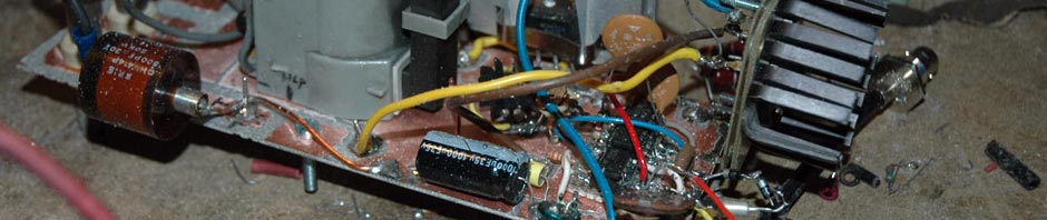
De spoel met parasieten
The biggest problem is the selfinductance from the wires, the unwanted coupling to unwanted/paracitic selfinductance causing mutual induction and of cause the paracitic capacitance (allthough a part of this is not a real capacitance, it does behaves like one)
Because there is coupling to and from the surrounding my idea was simple, just shield it and guard it. (to lower paracitics from the measurement set up). But this can and will cause eddycurrents in the metal. Now is that not always a big problem. As long as it is constant and of known magnitude you get get away with it in some cases. But it narrows down the use of it.
For a high selfinductance value you can make an inductor big. But besides not very handy it will require a lot of wire and/or a big housing. An other option is to use core material. And to spoil the conclusion; this is neither a perfect way. The problem with a core is that they work like a sort of selfinductance booster. Now you think, this behauviour is just what we want. We need not much wire so low ohmic loss, it needs not a lot of room and if we take a torroid we decrease the influence with the surrounding. So this sounds pretty good. The downside is the frequency and current dependency. By using a duplex winding the magnetic field that releates to the selfinductance is concentrated as much as possible to the torroid. I used Ferite for this experiment.
If you make a coil to test your standard LCR meter the frequency and current influence will be minimum. Most times 1 or 10 kHz with a very low current. But if you want it usable from 1 kHz to something like 10 MHz, it will be very, very hard to get it right.
The selfinductance from the wires between LCR meter and inductor, inside the cabinet and outside is a problem, or better, it can be a problem. For a 100 nH coil at 100 MHz this can be a huge problem, for a 1H coil at 100Hz this is not even a bit detectable.

Duplex winding
The parasitic self inductance inside the cabinet is not a problem in my case. It is just part of the value I measure if I consider the coil as a sort of black box for use within dedicated circumstances. But again, this can be a problem outside those circumstances. But to measure things like the mutual selfinductance you need to change wires and/or short things. To minimize influence from the outside the use of a shorting strap instead of reconnecting is the best solution. I use a seperate adapter for this but it can be integrated in the design itself like GR does. Because this is an experiment I wanted a cheap meatal cabinet. The one you see on the picture is a tincan used for food by Bon duel. The lid can be placed back in the can with a very tight fit. After doing that I fixated it with hotglue

Tincan and inductor

mounted inductor to the banana busses
As was to be expeded, its use is not very broad, but to use it at a fixed frequency for a bridge or LCR meter at as a sort of testcoil it is very usable. You can also use it for experiments or resonance measurement. It is easy to connect to a capacitor and not influenced by the surrounding. If you use several ways to measure it you can kinda calibrate it for frequency and current. To really calibrate it will be very hard, even if you have the gear.
The first thing you can do is using a torroid with known specs (so not tear it from an old TV but buy one from a known brand and type su you have the datasheet. This way the number of turns will give a usefull indication of the value.
You can measure it with a bridge or LCR meter and note frequency, current or voltage for the measured value.
The 3rd thing is resonating it with a known capacitor. Buy a good one, there are 1% capacitorsm, or measure it (also at several methods to destilate a usable average over frequency. Yes, always over a frequency span. The best cap will give the flattest frequency response. Choose a value that is usable for your coil. That is, the two are resonant at a usefull frequency. There is no use to resonate them at 100 MHz if you want the value at 1 kHz, besides that, you must be able to measure and generate that frequency.
If you find the resonance frequency ( by using some methode, like the griddipper way upto the network analyser way) you can calculate the L value because you know the frequency and capacitor. Using several capacitors you can make a L versus frequency curve if you want. You can measure a lot more if you like. For instance the selfresonance frequency, the real reasistance etc. By the way it is very educational to do figure out the real resistance versus frequency and compare that with the DC resistance. This way you see the effects caused by the skineffect and core losses.
Have fun experimenting with it.