
GR-1620A nog niet met de juiste bedrading
For a femto-Farad hunter like me this is the holy grail of capacitance measuring. There exists a model above this whit even higher specs but they are very rare. This bridge was upto 2002 used by Martron a ukas-lab in the UK, So, that was target market they made this bridges for. John Hersh designed it in 1962 and it is still in production. I think that is a very big accomplishment. General Radio is not more among us but the company who took over the bridge division is EIT Labs and the difference is the frontpanel is now white.
But why they would still make a piece of “antique” these days ? That is rather simple. Besides some disadvantages like huge, heavy, expensive, slow in use, it has a few very big pro’s. The accuracy is 0,01% and because the used standards and ratio-transformer it is 0.01% almost for ever. A ratiobrigde has very little problems with parasitic capacitance. Because the ratioarms are made from a transformer and taps the ratio is fixed and does not change over time. beside that, it has a very low impedance so a few pF stray capacitance does not matter. That will show up as a few MOhm parallel at a few mOhm.
The resulting |Z| does almost not change .

De ratio brug
There are many types of bridges. Some use only resistors, other resistors and reactances. But always the have two ratioarms. These can be variable or fixed. A variable capacitor, rheostat or transformer. Then there is a third are arm that contains a fixed or variable standard. The last arm is made from the unknown terminals. Complex Impedance bridges also have a compensating element. This to measure the phase difference so you can read D or Q.
The bridge itself is passive but it is feed by an internal or external oscillator, in this bridge it is external. In a classic Wheatstone bridge the current through both arms must be made equal so there is a balance between the two halves. The voltage at both measure points is then equal and the null detector meter zeros. You can make both halves equal in impedance but also different but with a same ratio between the high and low arm. So the current through the one half van be 1000x that of the other but because the ratio between top and bottom is the same in both halves the voltage at the measure points is still equal. This way you can get a very wide range.

Wat je eigenlijk meet
A capacitor is not only a capacitor. H and L in the picture above are the terminals for the unknown. H is High, the oscillator, L is low, the detector. But there is also a ground and a capacitor plate that has a voltage on it, has a capacitance to an other plate that has a lower voltage. Between H and L this is the case but also between H and ground and L and ground. The detector is very sensitive and has a high Z so the capacitance there towards the surrounding is critical. But there is also capacitance between the legs of the cap, between wires, between all those parts and ground ect
Beside that, the islation from a terminal or wire increases the capacitance. So the best way, besides guarded or shielded is using thin bare wire and metal terminals.
Also self inductance cancels some of the capacitance. At 1KHz this is not a big problem measuring a 1pF. The ESL is a few mOhm in serie with a lot of MOhms. But with a big electrolytic cap that introduces faults. (there are ways to calculate this, short the cap, measure its self-resonance. The R part is the ESR, the Xc and Xj cancel each other and with the known 1KHz capacitance you can calculate the self inductance and this way correct the appearent capacitance measured at other frequencies) but you still have other things to solve like changing dielectric constants through frequency, skin effect, ect
About D, the dissipation factor, a ratio that tells us something about the ratio resistance and reactance. So a D at 1KHz of 0.0001 and a reactance (1/(2pifC)) of 10000 ohm gives a ESR of 0.0001 x 10000 is 1 ohm. In other words 0.0001 x 100% is 0.01% of the power is dissipated in the cap. D is a number that is valid only for 1 frequency, in the case of most bridges 1KHz. For 10KHz you just multiply D x 10.
A lot of people tell you, but my modern LCR meter has a zero button. Yes that is correct and that is usable for non precision house and garden measurements but not for precision. It will go to deep to discus this here. I maybe once make a seperate topic about this.
Back to the GR. It is build up from three instruments. The ratiobridge, the power-oscillator and battery powered detector.

de detector GR 1620
This detector is super sensitive. It must be connected coaxial and uses 12V batteries because mains power holds to much noise. A mains cable hanging 50 cm above it allready influences the reading.
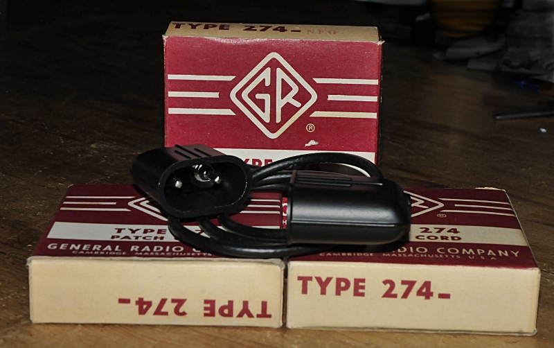
GR shielded banana casbles for the GR1620 and 1603
Finaly, thanks to Gerard, also a GR collector, I have the original shielded cables and the component holder
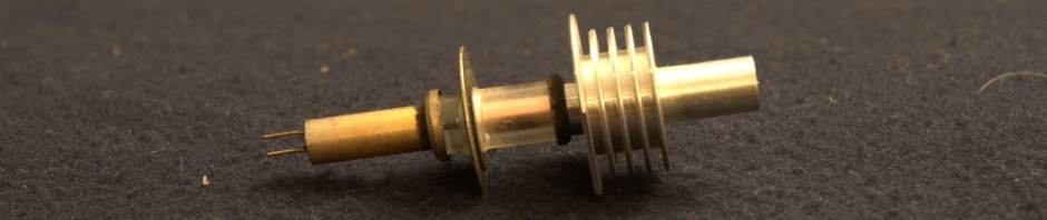
An accessoire for the GR-1620 and 1602 to shield components
The “screw” is a short

Specs van de GR1232A detector
This detector is also usable as AC amplifier and log detector.

Het principe van de detector, logamp en versterker
The oscillator is a juicy one, it is caple of making 100V and 4A (not at the same time)

GR-1311A Oscillator
It is connected through shielded cable with extra current chokes. On the picture the old situation. Now all is shielded including the terminals. It is capable of making 2 and 3 wire measurements. The 3 terminal is guarded. This cancels the influence of strays and EMI allmost complete.

Specs oscillator
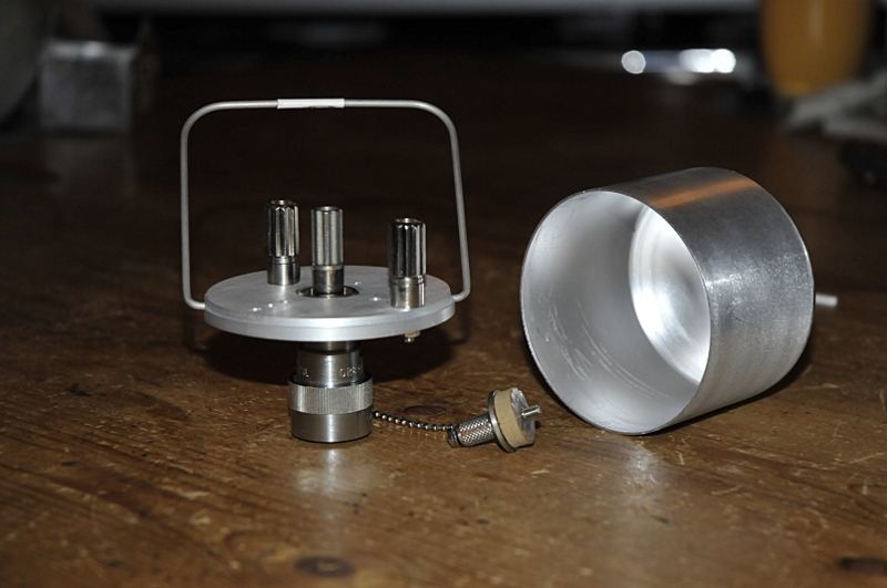
To make full advantage of the shielding I use a Faraday cup, a metal box that is on the guard potential. So allmost no strays. If I measure residu capacitnce at the banana terminals with nothing connected I get a few hunderd fF, at some bridges this is more as 4 pf, But in the faraday cup it is only 57.3 fF with the lid closed. , open 61.11 fF, a 3,81 fF difference.

De faraday cup of guard box en meerdere ingangen
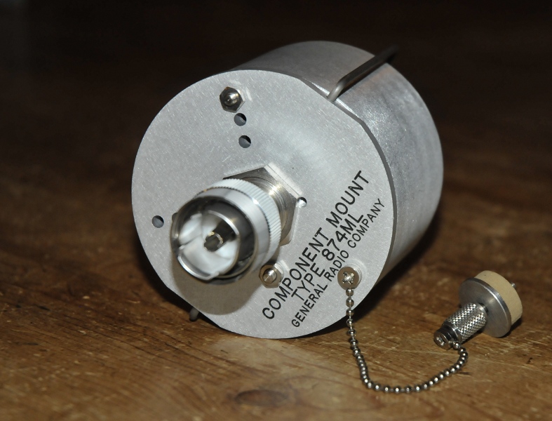
Some accesories to connect to the coaxial cables.

accessoires
The metal cabinet is for my VNA. The banana to coax looks a bit wierd but the guarding is going all the way down to the banana. Using three wire technic they must be connected to the case of the DUT. So that is why the one is looking strange folded back.This way the better stack.
The measurement range can be extended by the use of external standards. This option also makes it possible to compare or match caps to a high degree.

En natuurlijk de specs van de GR1615A brug zelf

De bedienings elementen.