Attention, some people want to build this to test the bandwidth of a scope. This is not the circuit for that. This is just a sort of honour to the late Jime Williams and build for fun. To test BW you need a fast puls but the pulse duration must be at least 5 times , or better 10X the bandwidt of the scope. So a step is better. If you use a fast short pulse the voltage goes up to the max value in a very short time. But if the puls is over the scope does not see a pulse anymore. If the puls stays long enough high the scope can continue to rise. If the amplitude then is equal to the puls it starts to follow and the pulse gets the form of a square, like is is. Now you can measure Tr and calculate BW. So if the step/square looks like a spike without a flat the pulse duration was to short. See more info about this here: http://www.pa4tim.nl/?p=434
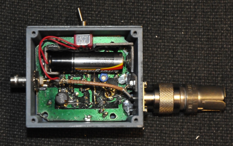
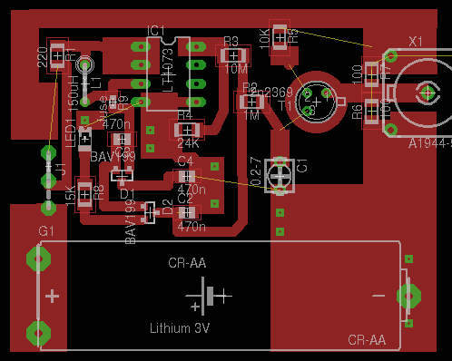
In Applicatie note 72 from LT Jim Williams designs a pulser needing a single 1.5V battery. A boost converter ( LT1073) and a cascade make 90V. This sets the 2n2369 in avelanche mode. The transistor sees a voltage just above its Vce breakdown voltage. The 1M resistor limits the current so it does not breakdown. The base is tied to ground through a 10K resistor. As soon as the junction breaks a fast pulse is formed. But this causes a voltagedrop over the 1M and voltage comes under breakdown level so the current flow stops. They pulse around 150-200KHz. The trimmer is to optimise the pulseform and voltage. With a 10X attenuator it gives me 400mV. Without attenuation this one makes it to 5V. Most Sampling scopes have a 2 or 3V input max and 50 Ohm DSO and normal analog scopes most times 5V max.

Pulser and psu

Schematic for details see app note Lineair Technology
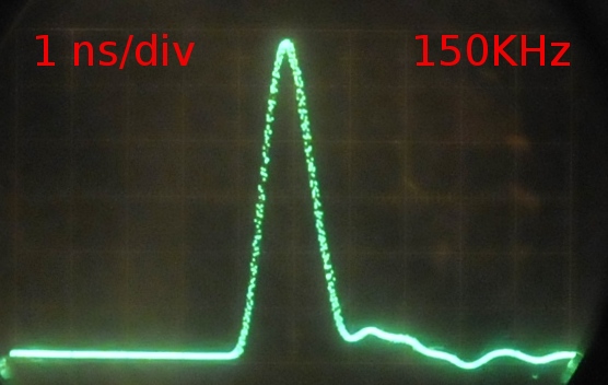
This is the result:

De hele puls.
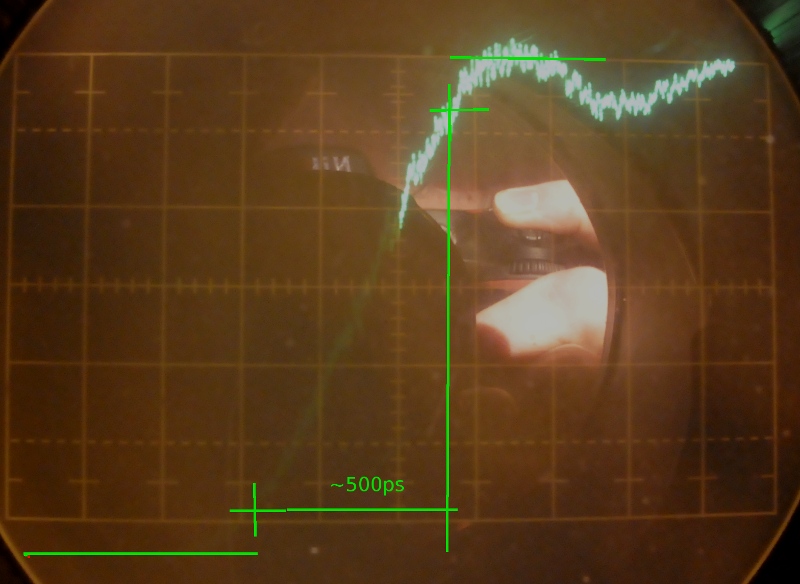
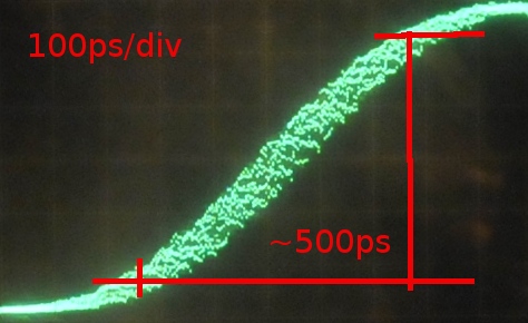
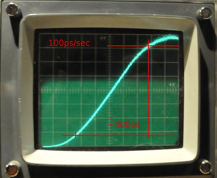
We want to know the ristetime:

100pS per divisie maakt 500ps
Update jan2013
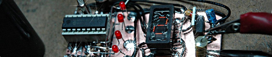
Version 2
I wanted to do some experiments using a chargeline to make a step out of it and to optimise the output. First the 2n2369 died because I forgot to reconnect the 1 M resistor. The datasheet of the regulator stated, in boost application there is no short circuit protection. I now know because it died too. Thanks to Blackdog from CO I had a new regulator and a couple of used 2n2369 transistors (by the way, a bsx20 does this trick too) He gave me some other fast transistors but only one 2n2369 dit avalance. The other 2n2369’s only started pulsing if I tapped the base or collector shortly with a screwdriver.

A little faster, more jitter
The old version was more stable. The new one, faster but not made deadbug and no shielded puls compartiment or decouple C has more jitter so I will try some decoupling too. The Tek sample plugins could not catch it. With some tricks I could see something and that showed 500, maybe 450 ps. thios is a result of many single shot pictures. Some showed 400-450 but were even more vague as the one down the DSO picture.

1ns/div, ugly bump on the falling edge
I made a 100K resistor on the output and to the bnc. This is a trigger puls but this has the same amount of jitter so no luck.
On a 350MHz oscilloscope while testing
This is with a 20dB attenuator. The Tr jumped between 800 and 1200ps because of jitter but it had no troubles triggering.
On a 1S1
Very bad PCB design
I’m terrible in making pcb’s. I first wanted to do thermal transfer but as usual without luck so I used the HP plotter. This, as usual, went very well. But I forgot to uncheck the mirror checkbox 🙁 so I had to mount the dual diodes upside down and the LT1073 at the other side of the pcb. The good thing was the transistor was right this way. I made a hole in the pcb for the collector. This was an idea from forum member Free Electron. I allready new the trick, I used it before but not in pulsers.
There is a fault in the pcb too pin 1 and 2 of the 1073 and parts involved should not be connected. (See schematic, is the same as version one ) . I noticed it before building and changed that using a dremel. The underside is copper but not under the transistor. The yellow lines are unconnected. I made a lot of vias to connect the groundplane instead.
Update:
I increased voltage to 102V. This gave a more stable frequency , added a 10 nF cap to filter the booster and changed the trigger pickup to 1K2
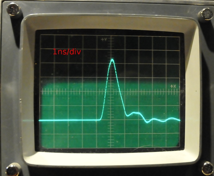
On a tek 1S1 after the modifications
No more snow, a clean pulse.
The Tr at the 1S1
A 500 ps Tr. And a realy nice curve.
At the 1 GHz Philips
The Philips agrees:
100 ps/div risetime measure
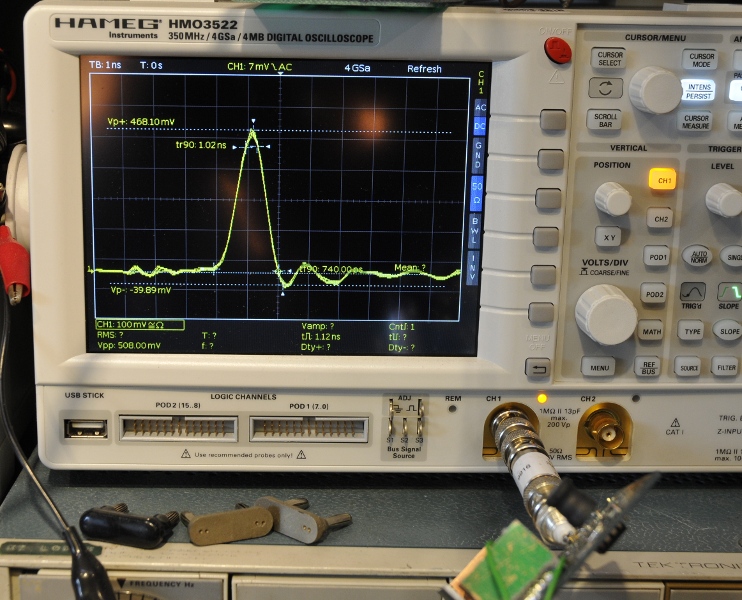
Now on a DSO, 350-MHz Hameg:
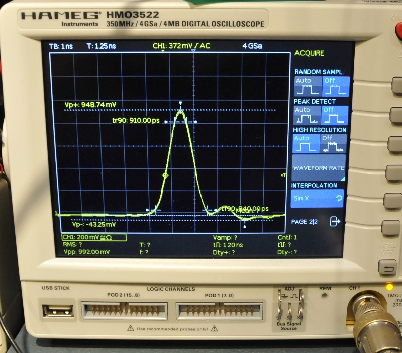
Hameg
The Hameg shows very good the form of the wave but Tr is much higher. Using the BW formula it would be over 440MHz. This because the pulse length is to short for BW measurements.
In action on my fastest scope at 50 mV/div. To my supprise this old 7MHz scope without trigger manages to capute a stable picture of this pulse. The attenuator is 10x so the pulse is 1,2V in real life
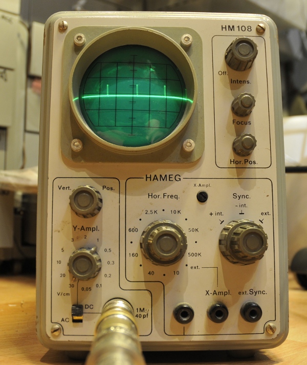
HM108 7 MHz scope at 50mV division (knob is mounted wrong)