Ehh, yes, it is difficult. But on the other hand, it is not. There are some, in base, easy methods but they are time consuming and measure the impedance. So the reactance and series resistance. This is not a real problem because reactance at low frequencies is high and resistance for good capacitors is low. And this is just an experiment I did befor I had my GR-1620 that has aF resolution. (this page was original written in Dutch and translated and updated in November 2013)
The biggest problem you need a well known small capacitor. And I did not have that. You can buy them but it looked like fun to make some. myself. By the way, later I used this technique to make filters for my DIY 2GHz sweep generator.
First attemp was to use two metal plates and make an air capacitor. But there was a small problem. I needed to attach wires to them and find a way to let them float in the air. That was a bit over the top so I looked for other ways. Standard buros use scalable capacitors made from 4 small tubes in a bigger tube. This also is way over the DIY limmit.

So I had to find an easy way that let me calculate the capacitance. My choiswe was FR4 PCB. I have enough of that and it is easy to make it the right size. In my innocence I thought this would be easy cause the K (dielectric constant, εr ) of FR4 in well known. It should be between 4.5 and 4.8. Oops, delta 0.3 is already a few pF difference…But there is more good news, FR4 is no real standard. It is typical between thos limmits, practical it can be anything.The amount of the stuff that hardens it influences the K and that can be something between 44-55%. On top of that K becomes higher when frequency goes down. (it can go over 5). I do not need to tell I had no clue about the PCB I had here.
After some math the followng result came up. But in the mean time I found out not only K is causing troubles in Paradise. I read horror stories about strays, edge effects, current spreading, dielectric loss changing under relative humidity and the influence from paracitic capacitance. For instance between test leads, terminals, metal objects on your desk, and let not forget they can work like an antenna.
I came up with the following values
C 1= 11,8945 pF
C 2= 28,6527 pF
C 3= 74,1789 pF
C 4= 7,0832 pF

The first test. I had a digital LCR meter from Voltcraft (also made under more brands). It has fF resolution but under 10pF it did not understand what I wanted from it.So what now ? I had a Marconi TF1313 bridge, (that lives with a friend now) not used much because they can be a bit overwhelming to use. ( At that time I did not know that in depth, If you know how they are great so I had to learn that first and that planted the seed of my .

This bridge can measure with 3 terminals in its lowest range with a 10 fF resolution and with a scharp eye you can get a digit more.
The values it gave:
C 1= 12,81 pF
C 2= 29,20 pF
C 3= 85,30 pF
C 4= 7,46 pF
The second methode was using a VNA. The problem is VNA’s are great in measuring impedances close to 50 Ohm. A 1pF capacitance at 10 MHz is not even close to 50 Ohm. But it can be done using the shunt methode. How to do that can fill a whole page so yiou have to believe me on this. I made a fixture that also has open, short and 50 Ohm for calibration purpose.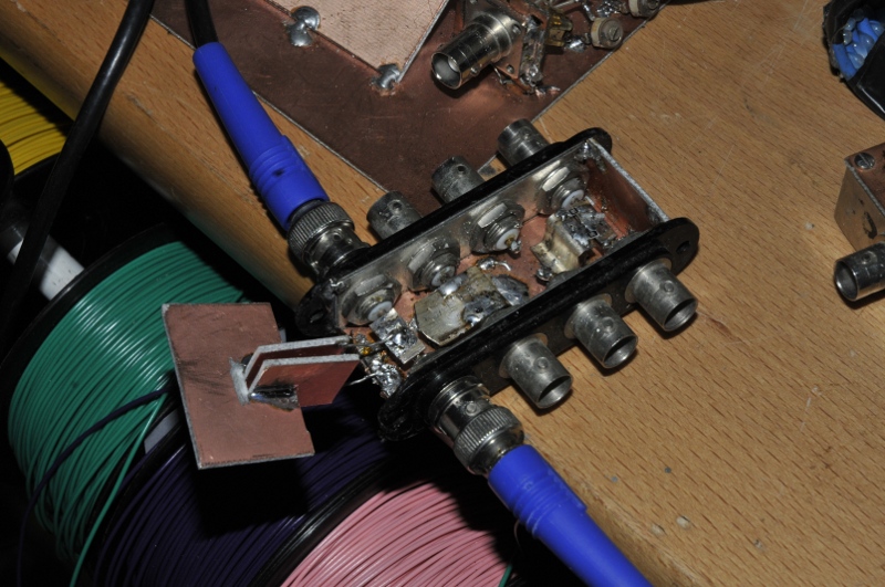
The top port is 50 Ohm, the second is open, the third is short and the last one is trough and made in a way I can solder a cap in shunt to it. The shunt is made by the 50 Ohm input of the RX port. So the VNA sees a big impedance in parallel with a 50 Ohm resistance. To do this perfect you need a few hours to set it up right and do verification tests, de-embeding etc.
The results are under the shunt methode simulation

C 1= 12,845 pF
C 2= 27,949 pF
C 3= 80,826 pF
C 4= 7,7848 pF

An other interesting methode is given by F.E. Terman in his book, measurements in radio engineering, he wrote in 1935. The principle is like most things from that area simple and elegant. You make an oscillator, note the frequency, add the cap and read the change in capacitance. If yiou choose the right values and frequency you get a direct reading meter. Because I have a calculator and a counter I did not bother about that. The oscillator was running at 11,097,594 Hz. The drift was a few Hz but it is just to see how it worked If you add the cap, the frequency drops. The strange problem was the oscillator took around 15 minutes to get back to the original frequency after removing the cap. Not a real problem because only the delta matters and you can note that befor.
Cz is the unkown DUT, Co, the oscillator cap, fo, the Original frequency and f1 is the frequency with the added DUT in parallel. Cz = Co x ( (( fo/f1 ) x ( fo/f1 ))-1 ) . This methode can get a very high resolution. Terman used an inductive coupled tank oscillator and a second reference oscillator together with a hetrodyne detector to tune for the beatnote. The Tektronix 130 LC meter uses this principle. I just used a counter.

Only probblem is you need to know the exact value of trhe inductor or capacitor of the oscillator. I used an oscillator I had build befor. So I had to do some tests and calculations to find the capacitance of the tank. It should be 136 pF. I was not interested in the excact value but the priciple.
This are the results:
C 1= 12,41714 pF
C 2= 28,46875 pF
C 3= 84,60578 pF
C 4= 7,811463 pF
Not bad…
I also used a sinewave generator running 50 kHz in series with a currentmeter and test cap. From the current you can calculate the impedance. I did not test it with these caps. You van also use a trms volmeter and measure the voltdrop over a series resistance. But this gave me the idea to make a IV meter or translate capacitance in frequency. The schematic down here worked in simulation but I did not build it. The top one is a CF converter, the second a IV converter. The idea was from Freddy from www. meettechniek.info


I have a Tektronix O-plugin. It has two valve operated opamps and the manual gave a methode to measure capacitance. I made an adapter for this. It is in the photo above. The sawtooth of the scope is used for this. I used 100Vtt for small caps and 10Vtt for big caps. You get a fixed delta V, made by the sawtooth, time is 1 ms. So the timebase gives you a fixed time and leave you with a fixed delta C
Vout = Rf x delta I and
Q=VC
i = delta Q / delta t
This way I could set it up to measure 1pF/div at 100V (0,1V/div=1pF/div) or 5pF/div at 10V (0,05V/div=5nA/div=5pF/div) .

Aint that cool, a C-trace on a 50 year old scope !! This gave the following results
C 1= 13,2 pF
C 2= 28,5 pF
C 3= 80 pF
C 4= 8,2 pF
One way everybody knows is the resonant frequency measurement. With a scope and generator. But this is not precise enough for fF because of paracitics and loading of the tank. But with a vna this is more easy
C 1= 12.86814 pF
C 2= 29,17389 pF
C 3= 73,29372 pF
C 4= 8,713196 pF
All results from all methodes together

As you can see, the results are pretty close. 500fF resolution after some finetuning is possible,. Things like shielding, guarding, better known paracitics and some known references can give you even better resolution withou buying an expensive LCR meter.

I made an other standard cap. At least I tried. It is very usefull but to bad, theory was way of the measured value. But it is stable and can be used as HV cap in transmitter. You can easy make it adjustable to. The plastic that enters or even comes closer increases the capacitance a lot.

It is around 20pF and around 50mm outerdiameter

The schematic above I made on a breadboard as test. The capacitance is direct reading in mV. 1mV is 10pF. I added a buffer between generator and capacitor. I used also a driven guard construction to cancel paracitic capacitance after the DUT. It worked well, even with a simple LT084 on a breadboad

The manual of the O-plugin showed an other methode. This also works good and over a broad range. Not as good for fF but still usable. The principle is easy. You see a squarewave after the cap. Measure its voltage on the CRT and calculate C:
Cz=(Vuit/Vin) X Cf
For instance you measure 1V and put 10V in it. The feedback cap was 100pF. 1/10=0.1 x 100 = 10pF. With a good fixture, guarding and shielding you can measure sub-1 pF

I did most measurements a few times and the table above is corrected because I could finetune things. Like the capacitor from the oscillator turned out to be 135,71 pF
The resonance measurement gave the less usable results. It is hard to not infleuence the tank by measuring. And that pulls it of frequency. I have allready made an article about that some time ago. It can be rather acurate but that involves a lot of work and gear. For measuring caps plus/minus a few pF it is a usefull way/

The breadboard concept worked so well I made a real meter out of it. It is build on double sided pcb. The bottom must be isolated from the rest because it forms a big capacitor to the inputs of the opamp. This also gives a lot of noise. Guarding is important because the signal you try to measure at 1 kHz is around 50 nA. It is not on the picture but I added some guard busses around the measurement input. It turned out this is not really needed. I used two peaces of shieldes wire as testleads. The coax shield is xconnected to the guard signal so shield and core are at the same level. If there is no voltage between two points there also is no capacitance,. The measure opamp is used inverting so the input is at ground level. This eleminates the input capacitance of the input.
I added a 5th order filter. I used a LT084 quad opamp. Better is to use separate opamps because of crosstalk. The amp is adjusted so that it gives 100 mV for 10pF, to calibrate it you can use a 10 MOhm resistor. By adjusting the amplitude of the generator to 1V you can measure caps upto the nF range.


Here you see 129.82 mVrms, so that is 12,982pF for een 12,417pF cap . A scope is not a 6,5 digit multimeter but it is cool to measurew fF with a scope and with very few euro in parts and a TRMS meter you can measure fF.
The whole pcb and cabinet is cleaned with IPA. It is build inside a metal enclosure including a +/-15V powersupply made out of a shielded transformer. I measure with 10Vtt at 1 kHz driven from a function generator. The front connector is isolated and the ground under the LF356 is removed to decrease capacitance as much as possible. This was an improvement.


The yellow triax cable goes to a 6,5 digit 6,5 digit TRMS meter. A 1 MOhm weerstand reads 159.155 mV. The reactance of a 100 pF capacitor is 1.591.549 ohm and 159,155 pF is 1 MOhm. Connect a resistor, adjust the voltage devider to 159,155 mV and your calibration is done.

An other experiment to measure dielectric constants. You measure it with the right gap, add some dielecric in between en measure the increase in capacitance. From the difference you can calculate the dielectric constant.
