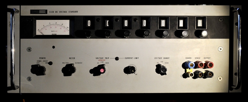
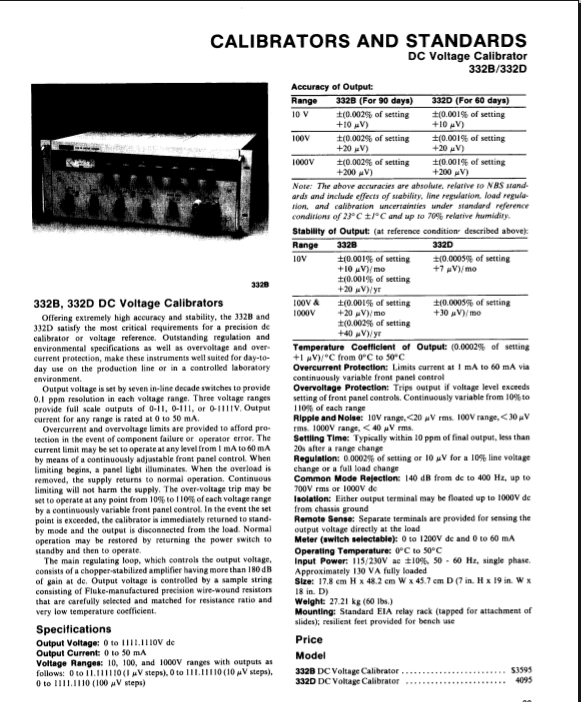
This is a 1973 Fluke 332B DC Voltage calibrator
Specs:
0-1111,1111 Volt and 0,002% precision. (20uV/V) internal decade for setting voltage. Current is adjustable (0,5 – 60mA) . This to protect the meter you are calibrating, if you get a bit over enthousiastic on the voltage Er zit een sense aansluiting op om kabelverlies te compenseren. De calibrator meet daIt has a sense and guard connection. The guard is driven with the same voltage and connected to the innershield. To use it the best you need special shielded low EMF cables and connectors.
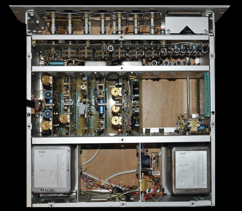
In this nice looking 30 kilo big box they mounted a second box. The chassis on the picture below is normally coverd with shield. Transformers are kept outside the guardshield. On this picture it misses 3 PCBs. The motherboard and the high voltage. They were faulty and that was one of the reasons I opened it. I have it from the first owner and it is not used since the 80’s. So I first had to check it and reform caps, clean it (allthough it still stood in the climate controlled lab) To remove those board I needed to desolder a lot of wires. That is not a problem but to connect them again is something else, you need three hands. The wires are kept as short as possible. The pcbs are sprayed with epocast, an epoxy. To replace a part you first must remove that stuff using a dremel with a brass brusch on it.
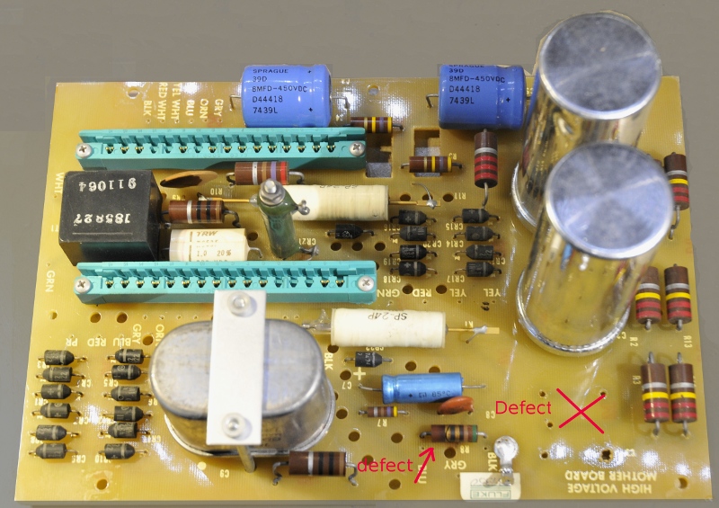
Thee caps were dead and one burned/cracked resistor.
I was lucky they gave me all the original documentents with the gear. I checked and cleand everything, checked the 15V Voltage reference using a Fluke 720 KV and 845AB against the Guildline standard cells (and later checked it against a calibrated 7,5 digit Prema and a fresh Keithley 2000) You also need to adjust all ranges using the Fluke 845 and you do not need other gear, just like a 720 this divider has a sort of self calibration (except for the 15V reference).
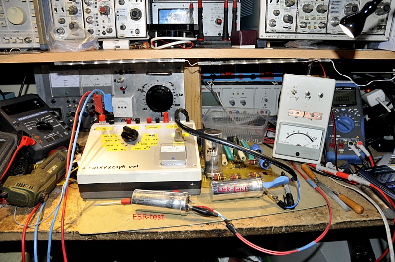
An important part of a restauration, checking the caps. The one on the leakage tester had a perfect ESR ,but to high leakage current. It also suffered from asomething that looks like dielectric absorbtion but is electrode ripture(16V in a few minutes and enough to light a LED and after an hour I tried that again but now a spark and the led was burned). Probably a partial ripped electrode. The electrodes are rolled in the paper-foil-paper- foil roll. The inner foil gets a bit compressed, the outer stretched. The ripture is then most times at the compressed point. An other cause is electrode erosion ,Then you get this schematic :
The left one is the one you measure and connected to the pins. The right one after the ripture of the foil. The RC above it is the ripture
You charge the cap, wait a while and decharge it. The left one looses its charge quickly, the right one then slowly charges the left one. Where is the ripture ? Suppose you charge it upto 100V, wait a few hours and then you measure 16V. The ripture is then at 100/16 from the foil lenght (this is the charge spread) (thanks to V. Himpe for the explanation)
A simple LCR meter does not always see this. You need one that gives you D and uses several frequencies. Sometimes they pressed rolls in a U form, that was the worst methode.
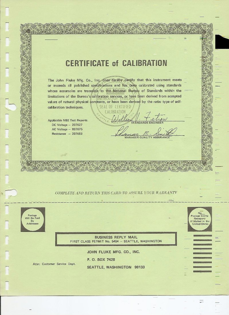
The certificate of calibration that came with it in 1974:

