This page is one of my pages about electrolytic caps. In this case DC leakage.
Instead of just replacing caps to be sure, I wanted to measure the DC leakage and for most be able to reform them. Electrolytics have two aluminium conductors separated by a some material holding electrolyte (which contains beside other stuff some salt like ingredients and water). Both are not very good isolators but as there is a voltage difference between the “plates” a chemical reaction takes place and an isolating oxide layer is formed on the metal. The oxide is a rather good isolator. This is also the diëlektricum ( and the diëlektricum is not, like many people think, the paper like separator in between layers) and they are very thin. Because the aluminium is etched, the holes formed increase it’s useful surface.
The factory forms the oxide layer (about 1.5 nm per Volt) by applying a voltage that is 135% up to 200% the maximum working voltage. After the capacitor is finished a good brand will “burn” it in by applying a Voltage lower as the working Voltage for some time.
If you apply this voltage to a cap that is long not used, it will conduct, heats up and the isolating layer will not reform. You just kill it that way. So you must limit current and slowly increase the voltage. The first 30 to 60 minutes are the most important. Also you need to go to just above the working voltage but not over the maximum voltage limit. During this proces a bit of the water vaporizes so you can not reform unlimited. Caps degrade faster when there are often long periods between use and non use.
I did a little test with a nos 47 uF 450 V cap. I applied 70 Volt in one time (current limited) it kept drawing 100uA. Then I discharged it to zero volts and applied 70V but this time in small steps over 15 minutes. The current dropped to almost zero at 70V. If I had applied 400V to it, I had killed it.
Besides DC leakage a cap can lose it’s capacitance or get a high ESR, (series resistance) see other parts of my site for more info about those subjects. Here I will tell about DC leakage and how to measure this. http://www.pa4tim.nl/?p=381 about ESR
failure modes:
– Good capacitance, high ESR, no DC leakage. Probably the anode connection is becoming bad.
– Capacitance a bit low, low ESR, DC leakage, This cap could be saved by reforming
– Capacitance real low (like a few nF instead of a lot uF), very high ESR, no DC leakage, the anode is ruptured. It is become a sort of air capacitor.
– Capacitance hard to measure, DC leakage very high, ESR super-low. Shorted cap, Probably you measure almost zero Ohm if you use a multimeter. It will charge more as a few mV while testing for leakage. This is rare for electrolytics but common for separation caps that where used in Valve equipment, or caps used between mains and chassis as filter at the mains entrance connector before they used X and Y caps.
Testing DC leakage:
The current you measure is at first high, if a cap is empty it behaves like a short, the inrush current is very high so you limit the current by a resistor. This is also a save way if a cap turns out to be a real short. The current drops over time depending on the RC time. Do not forget this. A 100uA current after two minutes can be 10uA after an hour. It depends on the voltage, current limits and capacitance. Datasheets often give a rule for this. Often they also give a time. Something like i=0.002CV, C in uF, i in uA. The factor 0.002 is model, type and brand dependent. Opposite to ESR and Capacitance this leakage does not become higher with age. (so more leakage is a sign to replace it)

I slaughtered a capacitor to show you its guts. One thing I can tell, it stinks and is a mess. I killed two, a good and a bad one. Both the same. The bad one had complete dry paper, the good one was a sticky mess.

The inside still surrounded by pressure tape. The tape holds the electrodes pressed together at the same distance for stability

The cathode ( minus lead) is connected via a strip to the cabinet and the lead for soldering on a pcb

When we remove the tape the cathode and its connection becomes visibele.

Unrolled we have 4 layers. The electrolyte is sucked in the “paper” between layers. An oxide layer is formed on both conductors so technical speaking the real capacitance is made by two caps in serie.

The centre of the cap. Here the anode is connected to the foil.
Testing and reforming :
For leakage testing you need to apply a DC voltage to the cap. If it is rated 100V it is possible it will still work great at 60V but starts leaking excessive at 75V. So we need an adjustable power source.
The first experiment was the well known classic tester using a neon bulb. There are commercial testers like Heathkit and Spraque made, but they are not always for electrolytic caps. GR made a capacitance bridge that also was able to measure DC leakage (GR-1617). These bridges are rare, I do not have one, but I would like to have one . Heathkit also made one with this function. (IT-28)
Using two 230-12V transformers while connecting the 12V outputs together coupled, gave me 230V isolated from the 230V mains. Then a diode to make DC and a neon light. When the cap is connected the neon light strikes and stays on until the cap stops drawing current. On small caps it is a very short flash, on big ones it takes a while. This only finds the really bad ones. Useful for finding short coupling caps in tube amps not for testing + 250V caps. I had a big 400V 40uF cap that smoked like hell and was to hot to touch. I later tested it to see if my testers ( neon light and Heathkit) were useful. They both failed and according to them the cap was still good. Also capacitance and ESR was OK. But using the right methode it was indeed leaking, but far above the test voltage of the other testers but below the working voltage of the instrument it was in.
If a cap is leaking, it still can have good capacitance and good ESR. You also can easy see if there is “soakage” or dielectric absorption, the cap holds it charge or recharges again. These can be different mechanisms but both not good if to much. There are tests for this too. Datasheets tell the conditions for this test. Most times they load it, unload it dead short and after a given time you must measure the voltage again.
Mike GE1DP has written a nice article about leakage. It is published in Vmars by Richard G7RVI . It is called How to avoid the big bang. His design used a two deck switch and a neon bulb. It can be a lot simpler. I used a 470 om resistor to ground and a meter across it to measure leakage current. I used a switch and two trimpots to get a 0-15mA and 0-750uA range, because that was the scale of my meter. I made a resistive divider that divides the 500V of my external psu in steps of 50V. Because I use an external powersupply I can also divide the 50 V in smaller steps by choosing a lower input voltage. The current measurement stays right. So no restrictions in what you want. If you only are interested in 50V caps, you do not have to change things. In my tester at 500V the max current is 25mA and I used 5W 2K2 resistors. The first one is 10W. (See below for updates on this project in progress)
The schematic:.

There is a rule of thumb about when a cap is leaking to much. Most old caps can be brought back to live this way (if they are long not used, but not if you already cooked them.)
The first half hour reforming is the most important, use a low voltage. The rest depends on the cap and how sure you want to be it will become OK again. Most times I take one or two hours. But if it is inside a very rare instrument that I want to keep original I sometimes use several days of loading and unloading and every time a bit more voltage.
The rule of thumb: uA=0,01 x C x testvoltage (C in uF and leakage in micro ampere) but this is for old caps and worse case. If i find a cap that is leaking more as 30-50 uA it goes in the wastebin ( but depends on its function) Datasheets often give a number for max leakage and shelf live. (after that time it needs to be formed again)
If you only need to measure this now and then there is a simple way using a multimeter. Use a powersupply and a resistor in series with the cap. Measure the voltage drop over the limiting resistor or connect a sensitive current meter in series. Old analog meters are often great for this.
Update 2011:
I made some changes, like the zero position now has a bleeder resistor to ground. And I made a second entrance for a 2000V powersupply. These are not in the schematic.

If you measure in situ you must lift on of the legs of the cap.
UPDATE JULI 2012
I made again some changes. The tester worked well but for reforming caps the 25mA was a bit more then needed and if it takes several hours the resistors get warm. Not to warm, but it is not necessary. Besides that it was not handy I had to use an external powersupply and extra leads. It is not handy to have two long wires through the lab that carry 500V (the PSU is good for 1A). So I wanted an internal supply. Problem was the space. I had two small 9V transformers, I mounted them back to back and the result was around 450V unloaded. But 450V and 25mA is a bit to much for those tiny things. So I changed the resistors. Now the current is limited to 1mA. More then enough for leakage testing and also nice for reforming. Only side effect is that leakage test takes a bit more time but I do not find that a problem. Also added an extra switch and some resistors to get three voltage levels that can be divided so now i can make 21 voltage steps.


Update may 2013: I placed by a wirewound potentiometer in the chain, so now I also can get every value in between.
Update 2016:
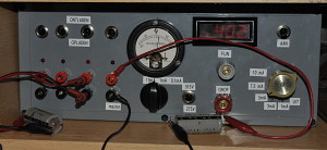
I made a new version. It has 2 voltage ranges and goes from 0 to 575V. It can deliver more current so I can do the correct leakage tests as stated in capacitor datasheets. (measure the current after 1, 2 or 5 minutes) It has three meter ranges: 10mA, 1mA, 100uA . I can reform 4 caps at the same time. The meter then shows the combined leakage for all 4. The voltage reading is a digital meter. The leakage meter is analog because that shows me better if the cap is stable.
Update 2021, The missing symbol to the right of the analog null meter is the ground symbol. The text from top to bottom 10 mA, 1 mA and 100 uA. It is a bit a mess around the meter because I changed the set up a few times while building. Originally I made the design for a digital meter. The had a meter with internal resistors and at6 the end an null meter. I forgot to change that in the schematic. If you use a normal analog meter you need to place resistors in series like I do in the passive tester above. I used a null meter so I can read the discharging current. The values depend on the meter you use. You can find the values with a powersupply, a DMM and a potentiometer in series with the analog meter. (or calculate them) Also add the 2 diodes for protection. While you discharge the caps without a null meter you can bridge the meter so it will not peg in the left corner trying to show the negative current. The discharge resistors must be able to dissipate the power and the value depend on how fast you want to discharge the cap.
I still use both testers without any problems

Using a multimeter and psu:
Down here I use a multimeter and powersupply to test high voltage caps from a scope. But you can also test normal caps using a normal low voltage bench supply. If you only use 16V caps you do not need 400V
By the way, 16V and lower rated caps are the least reliable.

http://www.pa4tim.nl/?p=1747 High voltage tester
http://www.pa4tim.nl/?p=985 Heathkit tester
http://www.pa4tim.nl/?p=114 schematics about how to apply the multimeter for testing
A very good document about LCR measuring:
http://www.ietlabs.com/pdf/application_notes/030122%20IET%20LCR%20PRIMER%201st%20Edition.pdf