This tracker I got from a friend who replaced the CRT but had no time and interest to make it work again.
A tracker is a sort of curvetracer (CT). They are also named octopus or component tester. Most Hameg scopes have one build in. The top in this field are from Huntron. This kind of CT have two outputs and are made to compare parts. The compare function switches between the outputs so you see the signatures (as they are called) more or less both at the same time at the same place. This makes it easy to see faults. They are ideal for repairing jobs where you have a working circuit to compare with the bad one. A second usable area are cases where you can not power up the problem circuit.
They are nothing more as a signal generator that set a voltage on a component and show that on the X Axis. They measure at the same time the current and show that on the Y axis. They use an AC signal. In this case a triangle. I think there are more 3110’s because I found a manual thanks to a reader of my site and that talks about a calibrated graticule and voltages and currents that are not even close to the ones in my 3110. (they state 18Vpp @ 250mAp, 60Vpp @ 2.5mAp, 120Vpp @1 mAp short circuit.)
If you short the probes the voltage will be zero and the current at max. This shows a vertical line. Open testleads have maximum voltage and no current. A flat vertical line is the result. The voltage starts negative and ends positive. It sweeps. So it shows the current that is the result of that sweep. A resistance will give a straight diagonal line. Most components show a characteristic figure called a signature. If you take a point at the tracer you have the voltage and current and Ohms law will do the rest.
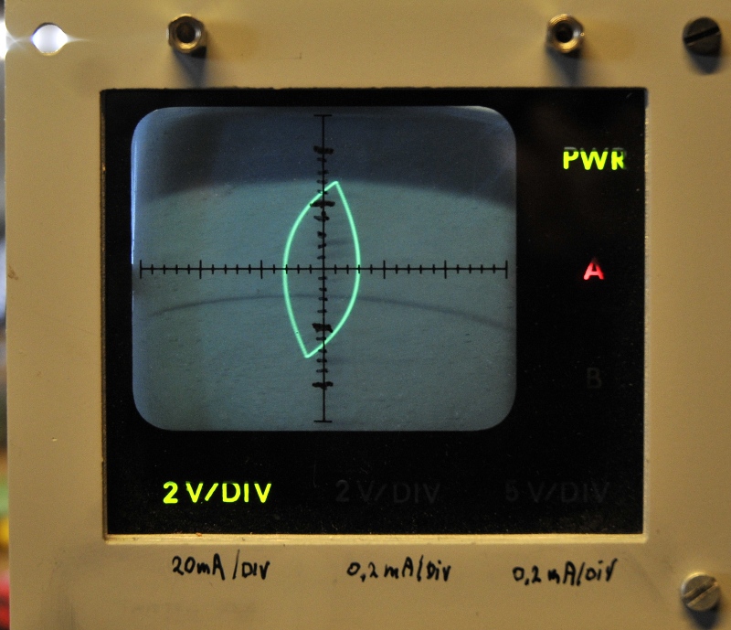
The signature above is porobably the most famous one. This is a zener diode. The zener starts conducting reversed biased at -0,6V. The Voltage stays about that but if the generator output rises the current does to. Hence the vertical line. In forward direction the zener does not conduct if it stays below the zener voltage. So the current is zero while the voltage increases. This is the horizontal trace. At the zener voltage the zener starts conducting. The resulting voltage stays constant, the increasing generator voltage increases the resulting current. And that is the vertical trace at the right. A capacitance and a coil show a circle. A normal diode looks like the left part of the zener.
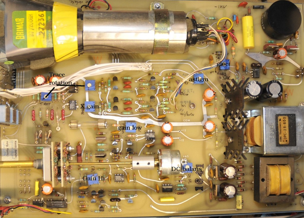
I had no manual so I had to sort it out myself. This is not very hard because it is not a very complex instrument. The hardest part is you do not know the exact voltages for generator and the psu. I made this photo with some data for those that have one without a manual too.
I had to set the CRT heater voltage with my tongue at the right angle at full moon because I had no clue what the unknown tube needed. I adjusted it for enough light and the most sharp trace.
There are 2 pots that cause trace rotation and a third on the front. The one close to the front seems to be the main pot. Set the frontpanel at 50% and adjust the other two. The most on top of the picture seems to be related to the high range. A bit strange. I think their main purpose is to correct the horizontal and vertical straightness of the trace.
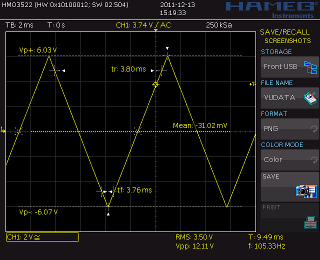
The output is a 100 Hz triangle .
position LOW: 12Vpp with the red knob at max. It is set with the Y gain low trimmer at 12Vpp on a scope. After third you set the DC balance trimmer so you have -6 to +6 . The vertical scale is 20 mA /div. (Mine has no divisions so I made them myself using a fine-liner.
Ranges:
Resistance 0-1000 Ohm
Capacitance: 10-200uF
Selfinduction: 1-200mH
Position MEDIUM: 12Vpp at 200uA/div . There are no trimpots. Mine does 13,3Vpp Probably some resistors out of tolerance.
Resistance: max 100K
Capacitance: 2n-10uF
Selfinductance: 2-40H
Positie HIGH: I think 30Vpp, but mine stops at 27,4V. As long as it aligns with the graticule there is no problem. The amplitude is set with the X-gain trimpot. I set it to 27,4 and a quick check for the low range looked good. This range is 200uA/div too.
Resistance: max 1M
Capacitance: 2n-1uF (a bit more resolution as Medium)
Selfinductance: >40H, or more accurate; huge.


