
Bob Pease circuit
If you have a short in a circuit there are several ways to find them. A short can be a bridge between 2 traces (solderblob or manufacturing fault) , a component (like a short cap) or a protection device that is “triggered” (like a TVS). It does not has to be between powerrail and ground but those are often the easy ones to find (often they give smoke signals).
But what if there is no smoke or blown fuse ? In that case you can use a thermocouple or other way to look for higher temperatures. Some people use thermal paper as an indicator to find a hotspot. This can be very handy to check a larger area in one glimp.
And then there are the cases non of the above work. Like in my case a short to ground in a signal path.
There are, besides the ones above, several ways.
You can use a multimeter with a lot of digits and a 4 wire connection. Every trace has resistance. If you connect one of the probes to ground (or an other net/trace if there is a short between to nets) and then measure the resistance between the 2 traces. The closer the probes come to each other the lower the resistance. So if you follow a trace you see the resistance decreasing until you reach the short. If you follow your trace the resistance will increase after the short. In that case you know there can be a “problem” at the lowest point. The problem is that resistance of a trace can be very low. You need around 1 mohm resolution.
A look at the inside
An other way is injecting a DC current into your short circuit and then measure the voltdrop over the traces. This is the same principle as the 4 wire resistance measurement. But this way you can use higher current to give you more resolution and you can use a not so exotic multimeter. The voltage you measure is the product of the trace-resistance and the injected current. So the closer you come to the short the lower the trace resistance will be. The voltagedrop will decrease to become almost zero at the short.
Problem for these methods is the high resistance protective layer over the pcb traces and you can not follow the signal on multi layer pcbs.
If you have a signal generator and a Spectrum analyser you can inject a signal within the bandwidth of the SA and follow it with a nearfield probe. The problem here is that a lot of components act as shorts for a RF signal. On the other side, it does not have problems with contact resistance or multi layers.
A better method is to use an audio frequency like 1 kHz and use an old cassette-read-head as probe. That is the thing that reads the magnetic fields from the audio tape. They are very sensitive. An AC signal through a trace will also generate a magnetic field. The downside is often the very low current from a function generator (besides that, not function generators like it to feed a short circuit) and the very low output of that magnetic probe. I used a Tektronix 1A7 uV plugin (10uV/div and very good adjustable filtering) . This works very well, you can trace multilayer boards but you still need to look at two points at the same time. (the pcb and the scope)
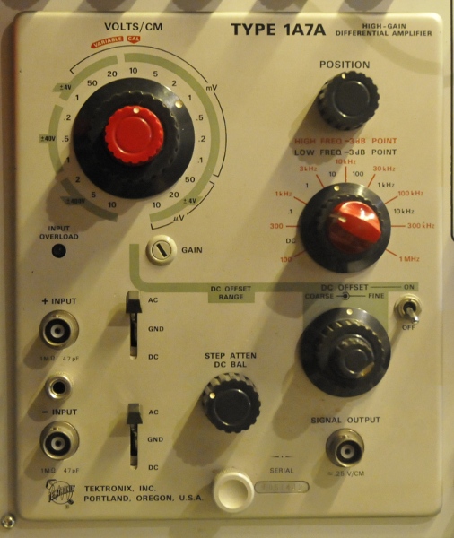
The Tek 1A7A
And that is the problem of all methods mentioned above.
Another exotic way it the use of a DC source and a hallsensor as detector. You need a very sensitive sensor and a very good amplification. A very good but very hard to make system.
Lets discuss some things that could be useful:
Beside eyes we have ears and those have a good resolution for the pitch or volume of a tone. So it would be nice to transform the test-result into a tone. The signals can be very small due to the low resistance so we need amplification.
To get more resolution it would be nice to use a bigger current source.
We do not want to heat up the short to much so we need some current limiting.
Pure AC is not very handy because it goes negative too but for most because we need a source that can supply enough and limited current.
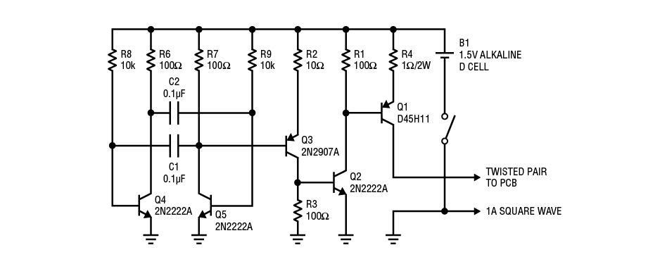
We do have a source that is perfect for the job, our lab-power supply. And if we switch that on/off we limit the effective current (and dissipation) while the higher peak current makes it more easy to detect it without to much exotic instruments. The way to do it is not very difficult. We make a high power wienbridge oscillator. Sounds complicated but it is nothing more as a handful of non critical general parts. And the nice part is, you do not need a lab power-supply. The circuit is designed for the use of a 1,5V D-cell. It can deliver upto 1A pulses. I used 5 relais and 5 different shunts so i can source 6mA, 30mA, 60 mA, 300mA and 700mA pulses.
The Bob Smith (LTC) version
To detect this signal we now can use a contactless methode because the pulsating current will generate a pulsating magnetic field. And we can detect pulsating magnetic fields rather easy with a coil. This method has more advantages. If we feed it through a capacitor we have an audiosignal and this removes any DC component that is formed during amplification. And we do not need to look at a meter. Our ears will do the detection.
The disadvantage is that it can be a bit noisy and also reacts at other AC signals. The advantage is that it is very sensitive and a coil is also direction sensitive. You can use it in a way that it picks up the signal around the trace but becomes silent exact above the trace. Or you rotate it 90 degrees and it will sound when you are exact above the trace. The sensitivity is not the same in both methods and that is the beauty of it. By using this we get a very flexible system that can be very useful to check if we got a false detection.
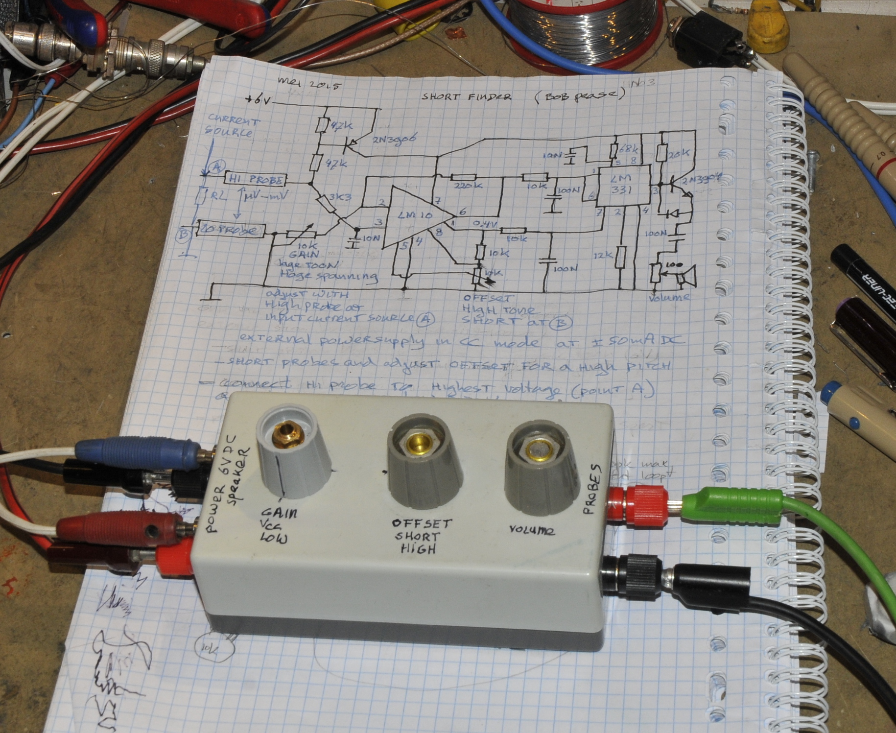
So after this theory it was time to fire up the soldering iron. You can not have to much instruments so I made 2. The first is a design from the book Trouble shooting analog circuits from the late Bob Pease. It uses a lab supply as current DC source. The detection is as brilliant as Bob himself. Nothing more as a precision opamp and a voltage to frequency converter. The advantages of this method is the almost bizarre resolution you can get with a 25 to 50mA source. It runs on 6V and uses almost no power while not probing so you can feed it with batteries if you want. It has enough power to feed a speaker. You first connect the probe to the low side of the current-source and adjust the offset potmeter until you get a high pitch. Then connect it to the high site and adjust gain until you get a very low sound. The resolution you can get is very high. From high to low can be in the uV’s. The downside is you must be able to physical contact the probe to the trace.
Wienbridge currentsource (Bob Smith)
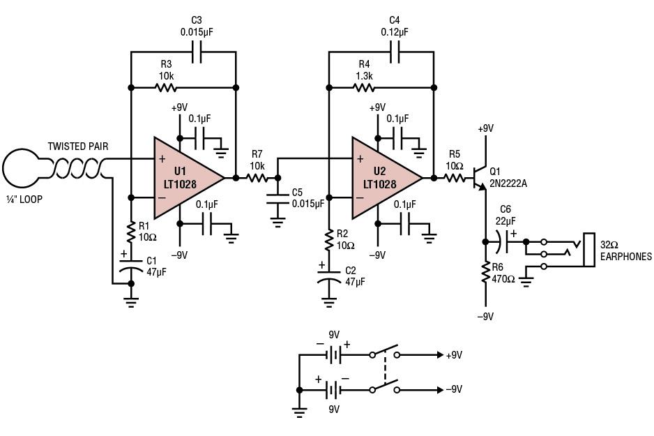
The probe amplifier (bob Smith)
The other circuit I build is from Bob Smith from Linear Technology Corporation (LTC) http://www.linear.com/solutions/5297
It uses a wienbridge oscillator with a 1,5V D cell and 5 transistors. The detection is done by two good opamps. It is a bit more noisy but it is very versatile. You can use the cassette recorder part, or several coils to make it more or less sensitive. The probe/amplifier is so sensitive you can use this for other tasks too. Like tracking a 1kHz test signal in an audio amplifier, or for reverse engineering a multilayer board. The tone you get is 800 Hz because that is the frequency of the wienbridge and the signal changes in amplitude. The closer you are to the short, the higher the amplitude will be. It has no problems with multilayers and there is no physical contact between probe and PCB under test.
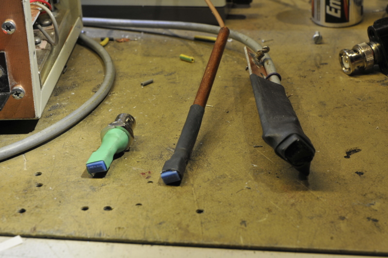
3 probes, the one on the right is the cassette recorder head
The left probe is a 3.3mH inductor soldered to a bnc connector. An easy way to make more probes, easy changing and a big choise in cable length. The second one is a 68mH inductor. This is the most sensitive. The most right one is the cassette recorder part. That is very directional so it only detects signals in one position and with high resolution in mm. It does not detect the 6mA singal. The 68mH one has no problem with that. The original schematic uses an air-coil and if you pulse with 1A it is probably sensitive enough. I do not like to use much current in things like calibration instruments (and repairing those is my job)
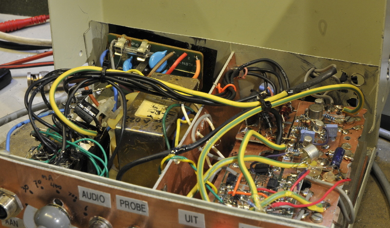
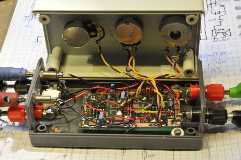
The inside
The left part is a transformer and the shunt relays, one the right, the current-source and probe amplifier. Under those are a 7809 and 7909 voltage regulator. I used other opamps (same class, ultra low noise versions from AD ) and a few other transistors (more powerfull version for the speaker) I did not leave space for a volume potentiometer because I do not use headphones but an old army speaker with volume knob build in and a bnc connector. The tests where done with a test speaker that always hangs above my head with bananajacks on the end of the leads. This is 8 ohm and that fried the original 2n2222 transistor in less then 20 seconds. It works really well and is very versatile.