GR-900 LB Slotted line
This is the GR-900 LB user manual (20 MB, over 80 pages in high res. Scanned by Guy, who also has a GR-900 LB. The user manual for this slotted line is rather rare so I placed it on my site, you can download it from here:
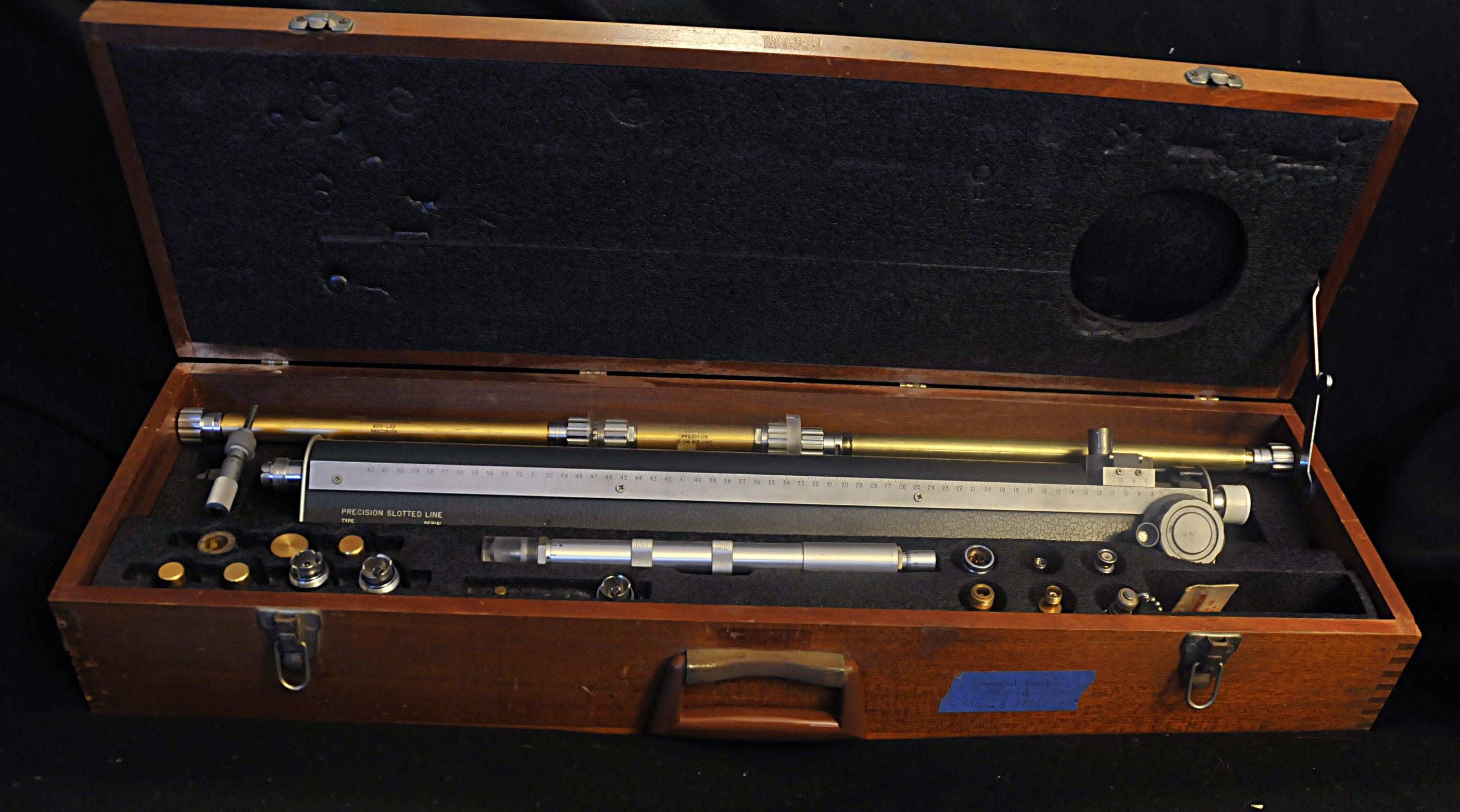
This is a General Radio GR-900-LB. One of the finest engineerd slotted lines in his time. Everything, from the wooden box upto the connectors is made beautiful. Today many people do not know what a slotted line is. Many decades this was “the” instrument you used in RF engineering.
It was used for things like adjusting antennas, component research, 1 port reflection, 2 port insertion loss measurements, calibration, measuring frequency.
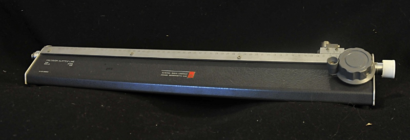
GR-900 LB slotted line
The beautifull thing of the slotted line is that it makes RF very visual. It is, to tell it a bit crued, nothing more as a piece of rigged coaxial transmission line. But it would be very hard to measure something in a piece of rigged coax without drilling a hole for your probe ( a lot of holes befor you find the points you want). To solve this they milled a slot in it, so you could poke around with a probe and measure the voltage over the whole lenght. When you connect a generator to the lefthand side and a 50 Ohm load to the right side and probe the slot you would measure the same voltage everywhere along the line. The probe is mounted on a carrier that travels from right to left along a ruler.
But if you connect a load to it with an other impedance as the line (50 Ohm), you get reflections. Often these are called standing waves. When you then probe the line from one side to the other you wil see the voltage go from minimum to maximum values. The minimums are all alike, the maximums too. The distance between every minima on the line is a fixed distance . The same is true for the maxima. If you would measure it along many points and put it in a graph you would see a stationairy wave. All tops alike in magnitude and all minimums too.
The need thing is that the distance between two equal magnitudes is half the wavelenght of the signal. So you realy measure the wavelenght as a distance using a ruler.
The ratio between the maximum magnitude and the minimum is the Voltage Standing Wave ratio. Voltage because that is what you measure, Standing wave because the wave is stationair and ratio, well, because that is what it is. Most time the minimum is used because that is more easy to measure.
But we can do more. We can measure the location of the first minimum using an open or short and then connect the DUT and measure the distance to the first mimimum again. This gives us the phase difference between a matched load and the DUT. The phase of the match we can not measure because the lack of standing waves, but a short and open have a known phase relation towards a perfect match.
The VSWR and phase is the base from where we can calculate things like Z, Y or Vf.
The knob you see at the right side is used to move the carriage that is mounted on the instrument and carries the probe.
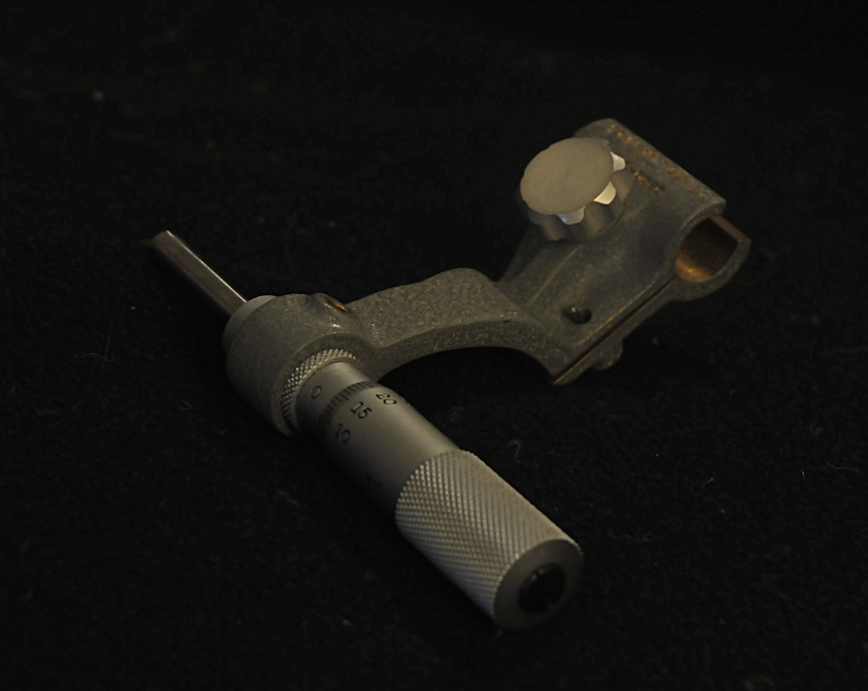
GR-900 detail micrometer
For more resolution you can mount this micrometer on the rod. This gives you a resolution of 0.001 mm. Besides the hardware showed above we need a source. The frequency must be between 300 and 8500 MHz. To read the voltage we need a detector. There is a build in detector and a position to mount an other detector or bolometer.
This detector needs an indicator like for instance a SWR meter , I have one from HP, or use the GR detector used for the GR1615 (with 1 uV resolution) or a DNT set (2 unit oscillators, MR mixer and IF amp/detector. The same set that is also used for the GR-1602B admittance meter.
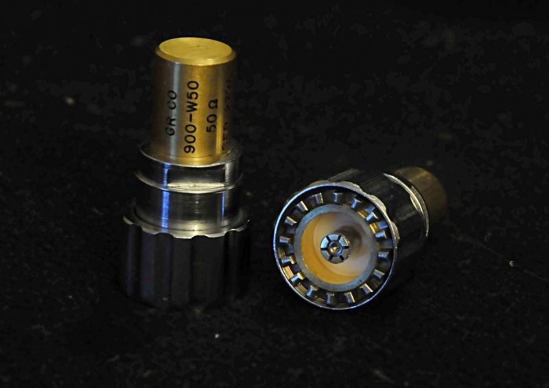
GR-900 W50 load
And you need some references. This slotted line can measure increadible low VSWR so it needs a very good reference. For this the GR-900 connector was made. This is, like the GR-874, a sexless connector with a very well defined reference plane. These are small mechanical wonders. The references are Load, short and open. Besides that airline is used.
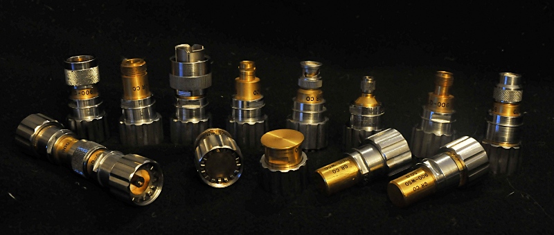
GR-900 adapter set
To connect a DUT with an other connector they made a GR-900 adapter set. High quality adapters with well known parameters. You see them in the picture above. On the left you see two adapters connected. In front you see the calibration kit. Open, short and two loads. There is a 100 Ohm load to make an excact known VSWR as check.
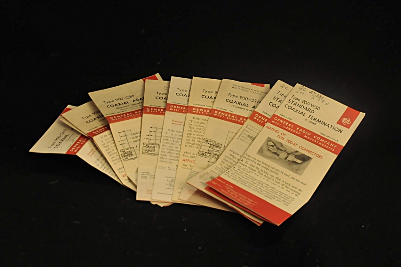
Papers of the GR-900 adapter set
These are the manuals from the adapters. They show specs and graphs.
To repair or take apart the connectors they made a beautiful toolkit.
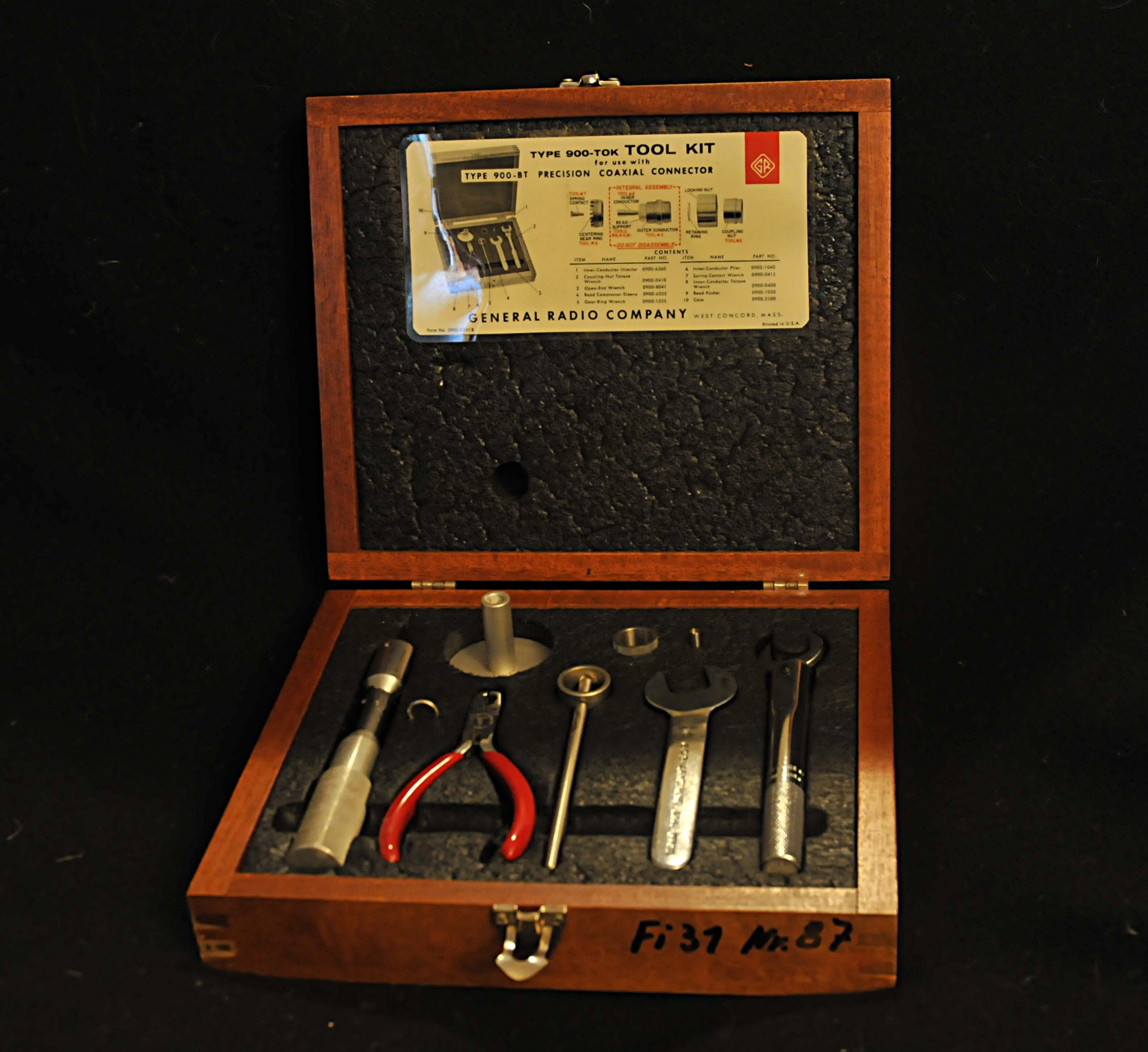
GR-900 TOK toolkit for GR-900 connectors
Left is a torque allan key, most right a torque wrench. The other tools are for taking apart or mounting every part of the connector.